NR Channel Coding: LDPC, Polar, MCS, and Link Adaptation Interview Prep
5G NR channel coding — LDPC for PDSCH/PUSCH data, polar codes for PDCCH/PUCCH control, MCS tables, CQI link adaptation, OLLA, and HARQ incremental redundancy.
Quick answer
NR channel coding is the FEC (Forward Error Correction) layer that adds redundancy to transmitted bits so the receiver can recover from channel noise and interference.
Channel coding is the deep-cut technical layer in 5G modem and PHY-engineer interviews — it integrates the math of FEC with the operational reality of link adaptation, HARQ, and MAC scheduling.
Editorial review
Written by
CompoundLearn editorial team
Wireless / RF / hardware engineering
Reviewed by
CompoundLearn editorial team
Wireless / RF / hardware engineering
Last reviewed
Built from curated topic maps, editorial validation, and subject-matter review so the page stays aligned with the interview intent and the current content pipeline.
What it is
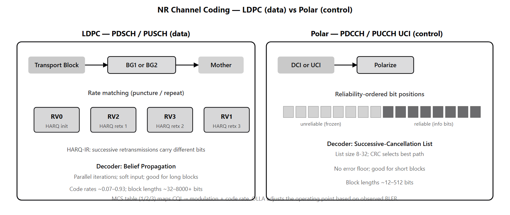
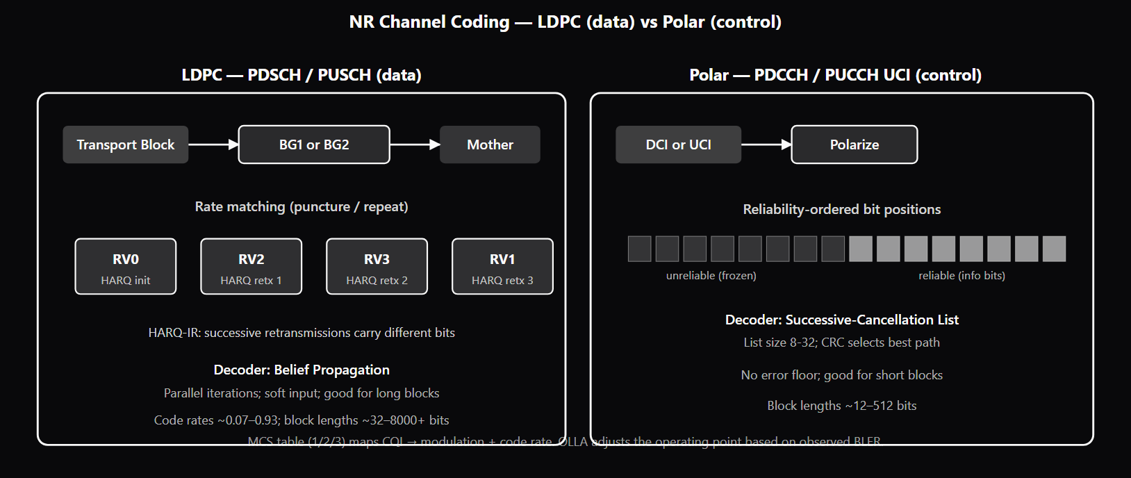
NR channel coding is the FEC (Forward Error Correction) layer that adds redundancy to transmitted bits so the receiver can recover from channel noise and interference. NR uses three code classes matched to different block-length regimes: LDPC for the long blocks carrying data on PDSCH and PUSCH, polar codes for the short blocks carrying control information on PDCCH DCI and PUCCH/PUSCH UCI (see /topics/nr-physical-channels), and Reed-Muller for the very short UCI payloads (1-11 bits) where polar would be overkill. LDPC (Low-Density Parity-Check) codes excel at long block lengths with iterative belief-propagation decoding that parallelizes well in hardware (see /topics/ldpc-codes-in-wireless). NR LDPC uses two base graphs: BG1 for larger transport blocks and higher code rates (typically TBs > ~3840 bits, code rates > ~0.67), BG2 for smaller TBs and lower code rates. The base graphs define the parity-check matrix structure; the actual code is constructed by replacing each non-zero entry with a permutation matrix. NR LDPC supports rate matching (puncturing or repeating bits to fit available resources), HARQ incremental redundancy (different redundancy versions for successive retransmissions), and code rates from ~0.07 (cell-edge with strong FEC) to ~0.93 (excellent-channel high-MCS). Polar codes excel at short block lengths under successive-cancellation list (SCL) decoding — typically list size 8-32. The defining property: by recursively combining a basic 2x2 transform, the channel polarizes so some bit positions are very reliable and others very unreliable; information rides on the reliable positions, frozen bits on the unreliable. PDCCH polar coding includes a CRC-aided list decoder where the CRC is used both for early termination and to pick the best path from the list. Polar codes have no error floor (unlike LDPC, which has known error-floor regions at high SNR), which makes them well-suited for control channels where the cost of decode failure is high. The MCS (Modulation and Coding Scheme) tables in NR map a 5-bit MCS index to a (modulation order, target code rate, spectral efficiency) triple. Three tables: Table 1 caps at 64QAM (default eMBB), Table 2 caps at 256QAM (unlocks higher peak throughput), Table 3 (qLowSE) targets 10⁻⁵ BLER instead of the standard 10⁻¹ (used for URLLC — see /topics/nr-urllc-mini-slot-preemption). The choice of table is RRC-configured per UE, and the gNB picks the appropriate MCS index per transmission based on CQI feedback and outer-loop link adaptation. Link adaptation has two loops. The inner loop uses CQI reports from the UE: CQI maps via a standardized 4-bit table to a target (modulation, code rate) combination that the UE can decode at the configured BLER target. The gNB picks an MCS index from the configured MCS table that achieves that target. The outer loop (Outer-Loop Link Adaptation, OLLA) tracks actual HARQ ACK/NACK and maintains an SINR offset per UE: NACK pushes the offset up (be more conservative); ACK pulls it down (be more aggressive). The increment-on-NACK and decrement-on-ACK are tuned asymmetrically so steady-state BLER converges to the target. Without OLLA, mismatches between CQI-implied MCS and actual channel BLER would persist — over-aggressive scheduling produces excessive HARQ retransmissions, over-conservative scheduling leaves throughput on the table. HARQ incremental redundancy is the retransmission strategy where successive retransmissions carry different bits (different redundancy versions) of the same encoded transport block. The first transmission carries RV0 (a subset of mother-code bits); retransmissions carry RV2, RV3, RV1 in turn. The receiver soft-combines all received versions, building up a stronger decoder input than any single transmission. HARQ-IR outperforms Chase combining because each new RV adds information rather than just SNR. The rate-matching procedure handles RV selection by mapping each RV to a different starting point in the mother codeword.
Why interviewers ask
Channel coding is the deep-cut technical layer in 5G modem and PHY-engineer interviews — it integrates the math of FEC with the operational reality of link adaptation, HARQ, and MAC scheduling. A candidate who fluently navigates the LDPC-vs-polar split, MCS table selection, CQI feedback semantics, and the inner-and-outer link-adaptation loops is showing the integrated PHY+MAC understanding that staff modem-design and PHY-engineer roles require. The LDPC-vs-polar split is the most-asked architectural question. Strong candidates explain that LDPC dominates the long-block data regime and polar dominates the short-block control regime, and that the split matches each code class to its strength (LDPC parallelizes for fast decode at long blocks; polar achieves capacity at short blocks with no error floor). Weak candidates name the codes without understanding the regime split. The MCS-table choice is the deployment-level question. Strong candidates explain that Table 1 / Table 2 / Table 3 correspond to 64QAM-cap / 256QAM-cap / qLowSE-URLLC operating regimes, and that operators configure per UE service class. Candidates who do not know that NR has three MCS tables or who treat them as interchangeable have not worked at the RRC-configuration level. The CQI-to-MCS-to-OLLA flow is the link-adaptation integration question. Strong candidates can describe the inner loop (CQI feedback → MCS selection) and the outer loop (OLLA — HARQ ACK/NACK → SINR offset → MCS correction) together, and explain why OLLA is necessary on top of CQI (CQI is quantized, channel changes between report and transmission, implementation has rounding). Candidates who name CQI without understanding OLLA miss half the link-adaptation system. HARQ incremental redundancy is the FEC-retx interaction question. Strong candidates explain that successive retransmissions carry different redundancy versions (different bit subsets of the mother codeword) and the receiver soft-combines them, building up a stronger decoder input than any single transmission. Candidates who describe HARQ as "send the same bits again" miss the IR mechanism that NR depends on. See /topics/harq for the cross-standard HARQ context. The polar SCL decoding question is the deep-PHY probe. Strong candidates can explain that polar SCL maintains a list of candidate decoded paths and uses the CRC to pick the best path from the list at the end. Candidates who know LDPC but not polar miss the control-channel half of NR FEC.
Common mistakes
The most common mistake is treating LDPC and polar codes as interchangeable. The split matches each code class to a specific block-length regime: LDPC for long-block data, polar for short-block control. Candidates who collapse the two or who claim LDPC is universal miss the architectural distinction. A second gap is missing MCS Table 3 (qLowSE). Most candidates know Table 1 (64QAM cap) and Table 2 (256QAM cap), but Table 3 is the URLLC-specific table targeting 10⁻⁵ BLER. Without Table 3 in the mental model, candidates cannot explain how URLLC achieves its reliability target with the same physical resources used by eMBB at 10⁻¹ BLER. A third gap is missing OLLA. Some candidates think CQI alone drives MCS selection; it does not. CQI is a quantized snapshot that doesn't perfectly predict actual BLER, and OLLA provides the closed-loop correction that keeps the link operating at the target BLER. Candidates who name "link adaptation" without explaining the inner-loop / outer-loop structure miss the operational reality. A fourth gap is conflating HARQ Chase combining with HARQ-IR. Chase combining retransmits identical bits; the receiver combines them coherently for SNR gain but the information content is unchanged. HARQ-IR retransmits different redundancy versions (different bit subsets); each new RV adds information, not just SNR. NR HARQ-IR is the default and outperforms Chase combining; candidates who describe NR HARQ as Chase combining have the wrong mechanism. A fifth gap is missing the rate-matching step. NR LDPC produces a fixed-length mother codeword that must be matched to the allocated PUSCH/PDSCH resources via puncturing (when allocation is smaller) or repetition (when allocation is larger). Different HARQ redundancy versions correspond to different starting points in the mother codeword. Candidates who do not surface rate matching miss a substantial piece of NR PHY-layer processing. A sixth gap is treating CQI, PMI, RI, and CRI as one feedback. They are separate quantities: CQI is channel quality (4 bits), PMI is precoder selection (variable bits depending on codebook), RI is MIMO rank (a few bits), CRI is CSI-RS resource indicator for beam management. Together they form the CSI report; the report quantity varies based on the configured CSI-ReportConfig. Candidates who collapse CQI and PMI miss the CSI framework structure. See /topics/nr-reference-signals for the CSI Framework context, /topics/harq for the cross-standard HARQ context, and /topics/nr-mac-scheduling for the MAC scheduler that consumes these feedback quantities.
NR Channel Codes — Use, Block Length, Decoding
| Code Class | Channels | Block Length | Decoder | Strengths |
|---|---|---|---|---|
| LDPC (BG1/BG2) | PDSCH, PUSCH (data) | ~32 to ~8000 bits | Iterative belief-propagation | Long blocks, parallel decode, soft input |
| Polar codes | PDCCH (DCI), PUCCH/PUSCH UCI | ~12 to ~512 bits | Successive-cancellation list (SCL) | Short blocks, no error floor, CRC-aided decoding |
| Reed-Muller | PUCCH UCI (very short) | 1-11 bits | Maximum-likelihood | Very short blocks, simple decode |
Sample interview questions
- 5G NR uses LDPC for data channels and polar codes for control channels. Why this split, and what does each code class do well that the other does not?
- A. LDPC and polar are equivalent; the split is historical.
- B. LDPC excels at large block sizes (hundreds to thousands of bits) with iterative belief-propagation decoding that parallelizes well in hardware — ideal for PDSCH/PUSCH transport blocks. Polar codes excel at small block sizes (tens of bits) with successive-cancellation list (SCL) decoding that achieves capacity at short lengths with no error floor — ideal for PDCCH DCI and PUCCH/PUSCH UCI. The split matches each code class to the block-length regime where it dominates: LDPC for the long-block bulk data, polar for the short-block control signaling. ✓
- C. LDPC is for downlink only; polar is for uplink only.
- D. Polar codes are the older code class being replaced by LDPC.
Option B is correct. The LDPC-vs-polar split in NR is one of the most-asked channel-coding interview topics because the choice is non-obvious and the rationale is technical. LDPC (Low-Density Parity-Check) codes: - Excel at large block lengths (hundreds to ~8000 bits typical in NR) - Iterative belief-propagation decoding parallelizes well across many parallel-running iterations - Soft-decision decoding is straightforward - Used for PDSCH (downlink data) and PUSCH (uplink data) — the high-throughput channels carrying transport blocks Polar codes: - Achieve capacity at finite (small) block lengths under successive-cancellation list (SCL) decoding - No error floor (unlike LDPC, which has known error-floor regions at high SNR) - Compact implementation for short blocks - Used for PDCCH (downlink control — DCI) and PUCCH/PUSCH UCI (uplink control — HARQ-ACK, CSI, SR) The block-length match is the technical reason for the split. DCI is small (tens of bits per DCI) and is always polar; UCI is polar-coded only when the payload is 12 bits or more, while very small UCI (1-11 bits) uses small-block coding (Reed-Muller / simplex / repetition) rather than polar. CSI and multi-bit HARQ-ACK reports in the 12-bits-and-up range are the polar regime. PDSCH/PUSCH transport blocks are thousands to tens of thousands of bits — the LDPC regime. Implementation depth: NR uses LDPC with two base graphs (BG1 for larger TBs and higher code rates; BG2 for smaller TBs and lower code rates), and polar codes with two construction variants (one for DCI, slightly different parameters for UCI). Both code classes are heavily optimized in hardware. Option A misses the technical rationale. Option C inverts the use — both LDPC and polar work in both directions; the split is by channel role (data vs control), not direction. Option D inverts code-class history — polar codes were proposed by Arikan in 2009, LDPC dates back to Gallager in 1960; both are modern in deployed terms.
- A UE reports CQI = 9 on a 10 MHz BWP at μ=1. The gNB then selects MCS index 16 from MCS Table 2 (256QAM table). What does the CQI report carry, how does the gNB use it, and what is the role of MCS table selection?
- A. CQI reports a 4-bit quantized channel quality that maps (via a standardized table) to a target combination of modulation + coding rate the UE can decode at 10% BLER. The gNB uses the CQI to choose an MCS index that targets that BLER on subsequent PDSCH transmissions. MCS table selection (Table 1 = 64QAM cap, Table 2 = 256QAM cap, Table 3 = qLowSE for URLLC) sets the modulation-ceiling and BLER-target regime for the UE. The pair (CQI table → MCS table) is operator-configurable per UE service class. ✓
- B. CQI reports the absolute SNR in dB; the gNB looks it up in a table.
- C. CQI is a feedback for HARQ retransmission only.
- D. CQI is the same as PMI; both report channel quality.
Option A is correct. CQI (Channel Quality Indicator) is a 4-bit value reported by the UE on PUCCH or PUSCH. Each CQI value maps via a standardized CQI table (defined in 3GPP TS 38.214) to a target (modulation order, target code rate) combination that the UE can decode at 10% BLER (or 10⁻⁵ BLER for the qLowSE table 3, URLLC). The MCS tables in NR: - **MCS Table 1**: Up to 64QAM (BPSK, QPSK, 16QAM, 64QAM). Used by default for typical eMBB traffic. - **MCS Table 2**: Up to 256QAM. Used when the UE supports 256QAM and the network configures it. Enables higher peak throughput when channels are excellent. - **MCS Table 3 (qLowSE)**: Lower spectral efficiency, targeting 10⁻⁵ BLER instead of 10⁻¹. Used for URLLC transmissions where one-shot reliability matters more than peak rate. The gNB uses CQI to select MCS as follows: 1. UE reports CQI based on its measurement of channel quality on the configured RS (CSI-RS or SSB-based depending on configuration) 2. gNB consults the CQI table to find the target spectral efficiency 3. gNB picks an MCS index from the configured MCS table that achieves ~ that spectral efficiency 4. Outer-loop link adaptation refines this — the gNB adjusts an offset based on observed actual BLER versus target CQI is a 4-bit (16-value) quantization; PMI (Precoder Matrix Indicator) is separate and selects the precoder; RI (Rank Indicator) selects the MIMO rank. Together CRI/RI/PMI/CQI form the standard CSI report (see /topics/nr-reference-signals for the CSI Framework context). Option B misses the table-mapping mechanism; CQI does not directly report SNR. Option C is wrong — CQI feeds link adaptation, not HARQ retransmission. Option D is wrong — CQI and PMI are different CSI report quantities. Production reality: CQI table + MCS table choice is one of the operator-tunable knobs per service class — eMBB uses Table 1 or 2 (10% BLER target), URLLC uses Table 3 (10⁻⁵ BLER target).
- Outer-loop link adaptation (OLLA) adjusts an SINR offset to keep observed BLER close to the configured target (e.g., 10%). Why is OLLA necessary on top of CQI-based MCS selection, and what happens when OLLA is disabled?
- A. OLLA is unnecessary; CQI alone determines the right MCS.
- B. CQI-driven MCS selection assumes the CQI report accurately reflects the channel quality at the moment the gNB schedules — but in practice the channel changes between report and transmission, the UE's CQI calculation has rounding error, and the CQI quantization is coarse. OLLA observes actual HARQ ACK/NACK and adjusts an SINR offset: NACK pushes the offset up (be more conservative); ACK pulls it down (be more aggressive). Without OLLA, mismatches between CQI-implied MCS and actual channel BLER produce sustained over-aggressive or over-conservative scheduling — either too many HARQ retransmissions (over-aggressive) or wasted throughput (over-conservative). ✓
- C. OLLA is a UE-side feature, not a gNB-side one.
- D. OLLA only operates in standalone (SA) deployments.
Option B is correct. CQI is a quantized snapshot of the UE's channel-quality estimate at the moment of measurement; it does not perfectly predict the BLER the gNB will actually see on subsequent PDSCH transmissions. Sources of mismatch: - Channel changes between CQI report and PDSCH transmission (CQI typically reports every 5-40 ms; PDSCH happens every ms) - UE-side CQI calculation has implementation-dependent rounding/clipping - CQI quantization is coarse (4 bits = 16 values for the whole quality range) - Interference conditions can change rapidly in dense deployments Outer-Loop Link Adaptation (OLLA) is the gNB-side closed-loop correction — a widely-used scheduler implementation technique rather than a 3GPP-specified algorithm (TS 38.214 standardizes CQI derivation and the CQI-table BLER targets, but not the OLLA update law): - gNB tracks per-UE HARQ ACK/NACK on initial transmissions - Maintains an SINR offset variable per UE - On NACK: offset increases (be more conservative — lower MCS next time) - On ACK: offset decreases (be more aggressive — higher MCS next time) - The increment-on-NACK and decrement-on-ACK are tuned so the steady-state BLER matches the target (typically 10% for eMBB) OLLA dynamics: the up-step on NACK is typically larger than the down-step on ACK (e.g., +0.5 dB on NACK, -0.05 dB on ACK) so the system reaches the BLER target asymmetrically. This produces ~10% NACK steady state — exactly the configured BLER target. Without OLLA, mismatches between CQI-implied MCS and actual channel BLER persist. Over-aggressive scheduling (MCS too high) produces many HARQ retransmissions, consuming resources that could have served other UEs. Over-conservative scheduling (MCS too low) leaves throughput on the table. OLLA is what keeps the operating point at the configured target. Option A misses why CQI alone is insufficient. Option C is wrong — OLLA runs in the gNB scheduler, not the UE. Option D is wrong — OLLA applies to all NR deployments regardless of SA/NSA. Production reality: OLLA tuning (step sizes, convergence rate, per-bearer BLER targets) is one of the most operator-customized scheduler pieces. URLLC bearers run OLLA against tighter BLER targets (10⁻⁵) using MCS Table 3.
Frequently asked questions
- What channel codes does 5G NR use?
- NR uses two channel-code classes: LDPC (Low-Density Parity-Check) codes for data channels (PDSCH downlink, PUSCH uplink) and polar codes for control channels (PDCCH for DCI, PUCCH/PUSCH for UCI such as HARQ-ACK and CSI). The split matches each code class to its block-length regime: LDPC excels at long blocks (hundreds to ~8000 bits) with iterative belief-propagation decoding; polar excels at short blocks (tens of bits) with successive-cancellation list decoding and no error floor. The Reed-Muller code class is also used for very short UCI payloads (1-11 bits) where polar would be overkill.
- What is LDPC in 5G NR?
- LDPC (Low-Density Parity-Check) is the channel code for PDSCH and PUSCH transport blocks. NR uses two LDPC base graphs: BG1 for larger TBs and higher code rates (typically TBs > ~3840 bits, code rates > ~0.67), and BG2 for smaller TBs and lower code rates. The base graphs define the parity-check matrix structure; the actual code is constructed by replacing each non-zero entry in the base graph with a permutation matrix. NR LDPC supports rate matching (puncturing or repeating bits to fit the available resources), HARQ incremental redundancy (different redundancy versions for successive retransmissions), and supports code rates from very low (~0.07, used for cell-edge with strong FEC) to very high (~0.93, used for excellent-channel high-MCS transmissions).
- What is polar coding in 5G NR?
- Polar codes (proposed by Arikan in 2009, the first capacity-achieving code class at finite block lengths) are used in NR for PDCCH DCI and PUCCH/PUSCH UCI. The defining property: by recursively combining a basic 2x2 transform, the resulting channel "polarizes" so some bit positions are very reliable and others are very unreliable; information is placed on the reliable positions, frozen bits on the unreliable. The decoder uses successive-cancellation list (SCL) decoding — typically with list size 8-32 — to achieve near-capacity performance at short block lengths with no error floor. PDCCH polar coding includes a CRC-aided list decoder where the CRC is used both for early termination and to pick the best path from the list.
- What are NR MCS tables?
- MCS (Modulation and Coding Scheme) tables map a 5-bit MCS index to a (modulation order, target code rate, spectral efficiency) triple. NR defines three tables: Table 1 caps at 64QAM and is the default for typical eMBB; Table 2 caps at 256QAM and unlocks higher peak throughput when the channel supports it; Table 3 (qLowSE, low spectral efficiency) targets 10⁻⁵ BLER instead of the standard 10⁻¹ — used for URLLC where one-shot reliability matters more than peak rate. The choice of table is RRC-configured per UE, and the gNB picks the appropriate MCS index per transmission based on CQI feedback and outer-loop link adaptation.
- What is link adaptation?
- Link adaptation is the process by which the gNB selects the modulation, code rate, MIMO rank, precoder, and number of layers for each PDSCH/PUSCH transmission based on the current channel quality. The inner loop uses CQI reports from the UE — CQI maps to a target (modulation, code rate) combination via a standardized table. The outer loop (OLLA — Outer-Loop Link Adaptation) tracks actual HARQ ACK/NACK and adjusts an SINR offset to keep observed BLER close to the configured target (typically 10% for eMBB, 10⁻⁵ for URLLC with MCS Table 3). Together inner-loop CQI selection plus outer-loop OLLA correction keep the link operating at the right point on the rate-vs-reliability curve.
- What is HARQ incremental redundancy in NR?
- HARQ-IR is the retransmission strategy where successive HARQ retransmissions carry different bits (different redundancy versions) of the same encoded transport block. The first transmission carries RV0 (a subset of the mother-code bits); the first retransmission carries RV2 (a different subset); RV3 and RV1 follow if more retransmissions are needed. The receiver soft-combines all received versions, building up a stronger decoder input than any single retransmission would provide. NR HARQ-IR is the default mode and outperforms Chase combining (where all retransmissions carry the same bits) because each new RV adds information rather than just SNR. See /topics/harq for the cross-standard HARQ context.
- What is rate matching in NR LDPC?
- LDPC produces a fixed-length "mother codeword" output per transport block; the actual transmission must fit the allocated PUSCH/PDSCH resources, which generally do not match the mother codeword length. Rate matching adapts: when the allocation is smaller than the mother codeword, the encoder punctures (drops some bits, prioritizing those on the lower-reliability LDPC bits); when the allocation is larger, the encoder repeats (sends some bits multiple times for additional energy). The rate-matching procedure also handles HARQ-IR redundancy version selection — different RVs correspond to different starting points in the mother codeword. Rate matching is a non-trivial part of NR PHY-layer processing and is implemented in dedicated hardware blocks in both transmitters and receivers.
- How does channel coding interact with HARQ and MAC scheduling?
- Channel coding and HARQ are tightly coupled: the channel code provides the redundancy that lets the receiver attempt to decode a noisy transmission, and HARQ supplements with retransmissions when decoding fails. The MAC scheduler (see /topics/nr-mac-scheduling) decides which UEs get which resources and whether to schedule a new transmission or a HARQ retransmission. The scheduler also selects MCS via link adaptation based on CQI feedback (see /topics/nr-reference-signals for the CSI Framework). The three layers — MAC scheduling, link adaptation (MCS selection), and channel coding (LDPC/polar) — work together: MCS sets the operating point on the rate-vs-reliability curve; channel coding provides the FEC at that operating point; HARQ retransmits when the chosen MCS turns out to be too aggressive. OLLA closes the loop by adjusting the operating point based on observed BLER.
Related topics
Siblings
- 5G NR Explained: Numerology, BWP, HARQ, and Frame Structure
- PDCCH, PDSCH, PUCCH, PUSCH: The 5G NR Physical Channels
- NR MAC Scheduling: PDCCH Allocation, BSR, DRX, Configured Grant
- LDPC Codes in Wireless (Wi-Fi 6+ / 5G NR / DVB-S2)
- HARQ (Hybrid Automatic Repeat reQuest)
- NR Reference Signals: DMRS, CSI-RS, SRS, PTRS, and the SSB
- Channel Estimation
- URLLC in 5G NR: Mini-Slots, Preemption, and Sub-1ms Latency
Practice
Essential AI-Native Skills for NR Channel Coding: LDPC, Polar, MCS, and Link Adaptation
Modern engineering work increasingly uses AI tools for design and code review, debugging, documentation, test and testbench generation, and workflow automation. The goal is not to let AI replace engineering judgment — it is to move faster while keeping verification discipline.
- Use AI to explain unfamiliar code, logs, waveforms, datasheets, or test failures.
- Break large problems into small, reviewable steps you can verify independently.
- Ask AI for hypotheses, then validate them against tests, measurements, simulations, or lab data.
- Version-control your analysis scripts, testbenches, and configs — keep changes small and reviewable.
- Document your assumptions, design tradeoffs, and debugging decisions.
- Verify AI output before trusting it: run the checks that fit the domain — unit tests, linters, simulations, or bench/lab measurements.
- Review AI output for correctness, edge cases, and real-world consequences.
NR Channel Coding: LDPC, Polar, MCS, and Link Adaptation — coming to the question bank
The adaptive practice engine is already live for core wireless, RF, and ML systems. NR Channel Coding: LDPC, Polar, MCS, and Link Adaptation isn't covered in the question bank yet — get notified when it's added.