NR Reference Signals: DMRS, CSI-RS, SRS, PTRS, and the SSB Interview Prep
5G NR reference signals — DMRS channel estimation, CSI-RS for CSI and beam management, SRS uplink sounding, PTRS phase tracking, and the SSB.
Quick answer
5G NR uses multiple reference signal (RS) types — DMRS, CSI-RS, SRS, PTRS, and the SSB — each serving a distinct purpose in the air-interface design.
Reference signals are the most-asked structural topic in 5G modem interviews because they are the layer at which every higher-level NR feature is measured and reported.
Editorial review
Written by
CompoundLearn editorial team
Wireless / RF / hardware engineering
Reviewed by
CompoundLearn editorial team
Wireless / RF / hardware engineering
Last reviewed
Built from curated topic maps, editorial validation, and subject-matter review so the page stays aligned with the interview intent and the current content pipeline.
What it is
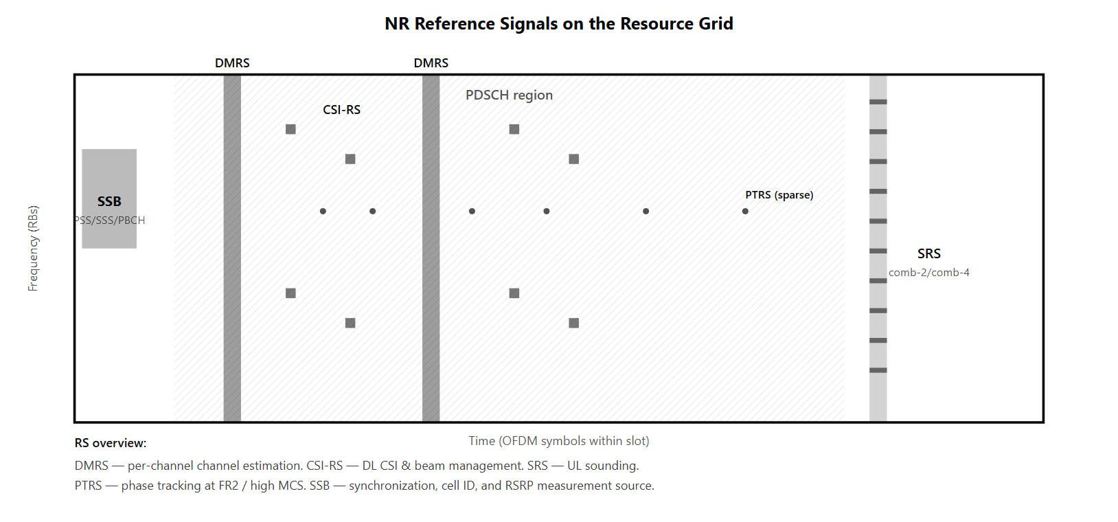
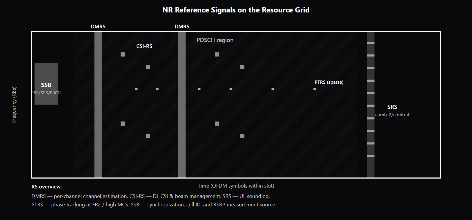
5G NR uses multiple reference signal (RS) types — DMRS, CSI-RS, SRS, PTRS, and the SSB — each serving a distinct purpose in the air-interface design. Understanding what each RS does, where it sits on the resource grid, and how it relates to the data channels is the prerequisite for understanding nearly every other NR topic: channel estimation, beam management, MIMO precoding, CSI feedback, and uplink scheduling all bottom out at an RS measurement. DMRS (Demodulation Reference Signal) provides channel estimation for demodulating each physical channel (see /topics/nr-physical-channels). Every NR data and control channel has its own DMRS — PDSCH-, PUSCH-, PDCCH-, PBCH-, and PUCCH-DMRS (PRACH is the exception: it uses preamble sequences, not DMRS). PDSCH/PUSCH DMRS are UE-specific and precoded with the data (the UE sees the effective post-precoding channel, which simplifies receiver design), whereas PBCH- and PDCCH-DMRS are not UE-specific. DMRS occupies specific OFDM symbol positions within the slot, and supports two configuration types: Type 1 (2 CDM groups, 6 REs/RB per CDM group; up to 4 ports with single-symbol DMRS, 8 with double-symbol) and Type 2 (3 CDM groups, 4 REs/RB per CDM group; up to 6 ports single-symbol, 12 double-symbol). The choice between Type 1 and Type 2 is a deployment-level decision balancing supported MIMO layers (see /topics/mimo) against RS overhead. CSI-RS (Channel State Information Reference Signal) is the downlink RS for CSI acquisition and beam management. CSI-RS configuration uses the CSI Framework — a set of RRC structures (CSI-MeasConfig, CSI-RS-ResourceConfig, CSI-RS-ResourceSet, CSI-ReportConfig) that bind CSI-RS resources to specific measurement and reporting behaviors. Tracking CSI-RS feeds CQI, PMI, and RI reports that drive downlink MCS selection and precoding. Beam-management CSI-RS is configured per beam direction so the UE can measure multiple candidate beams and report the best one (see /topics/nr-beam-management). CSI-RS supports periodic, semi-persistent, and aperiodic transmission, and a separate ZP-CSI-RS variant reserves resources to protect adjacent CSI-RS in neighbor cells. SRS (Sounding Reference Signal) is the uplink RS that lets the gNB measure the uplink channel. SRS configurations use a comb structure (typically comb-2 or comb-4) so multiple UEs can share the same SRS symbol on different combs without interfering. SRS drives uplink scheduling decisions, uplink-precoding selection, and — in TDD deployments where reciprocity holds — downlink-precoding selection. SRS supports periodic, semi-persistent, and aperiodic transmission, with aperiodic SRS triggered by a DCI from the gNB on demand. PTRS (Phase Tracking Reference Signal) is a sparse RS embedded in PDSCH or PUSCH transmissions to track slow phase drift within the slot. PTRS exists because local-oscillator phase noise at higher carrier frequencies (FR2 above 24 GHz) and higher modulation orders (64-QAM and above) is large enough between DMRS symbols to degrade EVM (see /topics/evm-error-vector-magnitude) and force the receiver to a lower MCS. PTRS density scales with the MCS and bandwidth, and PTRS is only inserted when the configured threshold conditions are met. The SSB (Synchronization Signal Block) carries PSS, SSS, and PBCH (with its own PBCH-DMRS). It serves as the synchronization and broadcast carrier during initial access, the RSRP-measurement reference for mobility events (RSRP_SSB), and the input for beam-management procedure P-1 (initial beam acquisition). The SSB is the only NR RS that bundles synchronization, system-information delivery, and measurement into one structure.
Why interviewers ask
Reference signals are the most-asked structural topic in 5G modem interviews because they are the layer at which every higher-level NR feature is measured and reported. Channel estimation, MIMO precoding, beam management, CSI feedback, and uplink scheduling all live on top of an RS — and a candidate who cannot describe which RS feeds which feature has not yet built a mental model of the air interface. The DMRS Type 1 vs Type 2 trade-off is probed because it is one of the more concrete configuration decisions an operator makes. Strong candidates describe the (port count, RE overhead) split — Type 1 lower overhead but fewer ports; Type 2 more ports for higher-order MU-MIMO at higher overhead — and can identify when each is preferred. Weak candidates treat DMRS as a single configuration without naming the types. The CSI Framework is the most-complex single configuration block in NR RRC, and interviewers use it to probe whether a candidate has worked at the configuration layer. Naming CSI-MeasConfig and CSI-ReportConfig, knowing the difference between periodic / semi-persistent / aperiodic reporting, and explaining how a CSI report binds to a CSI-RS resource set is the level of detail that distinguishes serious candidates. PTRS is the deep-cut question — many candidates know DMRS, CSI-RS, and SRS but have not heard of PTRS or do not know what motivates it. A candidate who can explain that PTRS exists because phase noise within the slot at FR2 carrier frequencies degrades high-order modulation, and that PTRS density scales with MCS, reveals exposure to mmWave deployments specifically. The CSI-RS dual purpose (tracking vs beam management) is the design-rationale question. Candidates who treat CSI-RS as a single resource type without explaining the resource-set tagging miss the architectural split between CSI feedback (for MCS/precoding) and beam measurement (for beam selection). The CSI-ReportConfig.reportQuantity field is the configuration parameter that distinguishes the two.
Common mistakes
The most common mistake is naming DMRS without describing the configuration types. DMRS Type 1 and Type 2 are different orthogonal-port-count/RE-overhead designs, and the operator selects per scenario — Type 1 for typical SU-MIMO, Type 2 when more MIMO layers are needed. Candidates who describe DMRS as a single structure miss the planning decision. A second gap is missing the CSI Framework. Candidates who describe CSI-RS as just "a reference signal for CSI" without naming CSI-MeasConfig, CSI-ReportConfig, or the periodic/semi-persistent/aperiodic distinction have not worked at the RRC configuration layer. The CSI Framework is also the layer that ties CSI-RS to beam management, so missing the framework means missing the bridge between RS configuration and beam-management procedures. A third gap is missing PTRS entirely or misunderstanding what it tracks. Candidates who confuse PTRS with TPC (Transmit Power Control) — phase tracking versus power tracking — or who name PTRS without explaining that it exists for high-frequency phase noise reveal a thin understanding of FR2 deployment constraints. A fourth gap is treating CSI-RS as a single-purpose RS. CSI-RS for tracking (feeding CQI/PMI/RI for MCS and precoding decisions) and CSI-RS for beam management (feeding RSRP per candidate beam direction) use different resource-set configurations and different report quantities; the architecture separates them deliberately. Candidates who describe CSI-RS as "the CSI feedback RS" miss the beam-management role. A fifth gap, common in candidates with LTE backgrounds, is assuming NR DMRS and LTE CRS work the same way. NR replaced LTE's always-on Cell-specific Reference Signal (CRS) with on-demand DMRS plus CSI-RS — a deliberate change that reduces always-on overhead and supports lean-carrier operation. Candidates who describe NR as having CRS or who do not know that always-on CRS was removed reveal a transition gap in their NR knowledge.
5G NR Reference Signals — Role, Direction, and Configuration
| RS | Direction | Purpose | Configuration Layer | Periodicity Options | Multiplexing |
|---|---|---|---|---|---|
| DMRS | DL + UL (per physical channel) | Channel estimation for demodulation | Channel-specific (PDSCH-DMRS, PUSCH-DMRS, etc.) | Per-channel transmission (no separate periodicity) | OFDM symbol positions + ports via OCC |
| CSI-RS | DL | CSI acquisition (CQI/PMI/RI), beam management | CSI Framework (RRC) | Periodic, semi-persistent, aperiodic | Configurable RE positions + ZP-CSI-RS protection |
| SRS | UL | Uplink channel sounding for scheduling and TDD reciprocity | SRS-Config (RRC) + DCI trigger for aperiodic | Periodic, semi-persistent, aperiodic | Comb structure (comb-2 / comb-4) |
| PTRS | DL + UL (rides on PDSCH/PUSCH) | Phase-noise tracking within the slot | Configured threshold MCS + bandwidth | Inserted per scheduled transmission when configured | Sparse REs distributed across slot |
| SSB (PSS/SSS/PBCH-DMRS) | DL | Synchronization, cell ID, beam measurement, RSRP | Cell-level (transmitted regardless of UE) | SS burst set periodicity (typically 20 ms) | Dedicated 4-symbol structure |
Sample interview questions
- A UE is configured for DMRS Type 1 versus DMRS Type 2 for PDSCH. What is the practical trade-off between the two configurations?
- A. DMRS Type 1 supports up to 8 orthogonal antenna ports using 6 REs per RB per symbol; Type 2 supports up to 12 orthogonal ports using 4 REs per RB per symbol — different (port-count, RE-overhead) trade-offs. Type 1 is the default for most deployments; Type 2 is preferred when more MIMO layers are needed (e.g., higher-order MU-MIMO). ✓
- B. DMRS Type 1 uses more REs per RB than Type 2, so Type 1 supports more orthogonal antenna ports but costs more overhead.
- C. DMRS Type 1 is for downlink only; Type 2 is for uplink only.
- D. DMRS Type 1 and Type 2 are identical; the type number just selects different scrambling sequences.
Option A is correct. The two DMRS configuration types differ in the (RE pattern, port count) trade-off. Type 1 uses comb-2 patterns where each port occupies 6 REs per RB (within one DMRS symbol), supporting up to 4 orthogonal ports per CDM group with 2 CDM groups and 8 total ports across both groups. Type 2 uses denser RE packing within fewer REs (4 REs per RB per symbol per port) and supports up to 6 ports per CDM group with 2 groups, totaling 12 ports. When each is preferred: Type 1 has fewer ports but lower overhead — adequate for single-user MIMO and most SU-MIMO configurations. Type 2 supports more orthogonal layers, which matters for higher-order MU-MIMO where the gNB needs to separate many UEs spatially in the same time-frequency resource. Operators select per deployment scenario. Option B inverts the relationship — Type 1 uses 6 REs per RB per symbol, Type 2 uses 4. Option C is wrong — both types are defined for both UL and DL DMRS. Option D collapses real architectural differences into a labeling choice. Production reality: DMRS overhead is a meaningful share of the resource grid (especially with additional DMRS symbols for high-Doppler scenarios), so Type 1 vs Type 2 selection is a real planning decision in dense MU-MIMO deployments.
- Why does NR include PTRS (Phase Tracking Reference Signal) as a separate reference signal alongside DMRS?
- A. PTRS is redundant with DMRS and is only included for backward compatibility with LTE.
- B. PTRS tracks slow-varying phase noise across the slot — DMRS provides channel estimation only at its configured DMRS-symbol positions, but at higher carrier frequencies (especially FR2 with high SCS) the local-oscillator phase noise drifts within the slot enough to degrade high-order modulation (64-QAM, 256-QAM). PTRS samples the phase drift on a sparse grid (time density set by MCS thresholds, frequency density by scheduled-bandwidth thresholds) so the receiver can interpolate and correct. ✓
- C. PTRS is only used for uplink power tracking, not phase tracking.
- D. PTRS is used for paging only.
Option B is correct. The motivation for PTRS is phase noise: at FR2 carrier frequencies (24+ GHz) the local-oscillator phase noise within both the UE and the gNB drifts during a slot. DMRS provides one (or two, with additional DMRS symbols) snapshots of the channel per slot — enough for initial channel estimation but not for tracking the within-slot phase drift that high-order modulations are sensitive to. PTRS adds a sparse set of pilot REs distributed across the slot so the receiver can interpolate the phase drift between DMRS symbols and correct it before demodulation. PTRS density scales with the MCS (higher MCS → more PTRS REs because higher-order modulation is more phase-sensitive) and the scheduled bandwidth. PTRS is configured for both PDSCH (downlink phase tracking) and PUSCH (uplink phase tracking); whether it is actually inserted in a given transmission depends on the configured threshold MCS and bandwidth. Option A misses the technical need entirely. Option C confuses PTRS with TPC; PTRS is for phase tracking, not power tracking. Option D is wrong; PTRS rides on PDSCH/PUSCH, not paging channels. Production reality: PTRS overhead is small (the RE count is sparse) but it is the difference between 64-QAM and 256-QAM being usable at FR2; without PTRS, phase-noise-driven EVM degradation pushes the achievable MCS down.
- A gNB uses CSI-RS for both downlink CSI acquisition and beam-management measurement. How does the configuration distinguish these two purposes?
- A. CSI-RS is a single resource that serves both purposes simultaneously — no configuration distinction is needed.
- B. CSI-RS for beam management uses a different waveform than CSI-RS for CSI acquisition.
- C. CSI-RS resources are organized into resource sets bound to CSI-ReportConfig structures, and the report's reportQuantity is what distinguishes the purpose: a report with reportQuantity CQI/PMI/RI/CRI drives CSI acquisition on the active beam (feeding MCS and precoding), while a report with reportQuantity cri-RSRP (or ssb-Index-RSRP) drives beam management — the beam-management resource set is configured per beam direction so the UE can measure each candidate beam and feed back the best one. (The resource set's repetition flag separately signals whether the resources share the same downlink spatial-TX filter.) ✓
- D. CSI-RS is only used for beam management; CSI acquisition uses SRS instead.
Option C is correct. CSI-RS resources are configured at the RRC layer and grouped into CSI-RS resource sets. Each resource set has a configured purpose: tracking (used for CSI reporting on the active serving beam — CQI, PMI, RI feedback that drives MCS selection and precoding), or beam management (used for measuring multiple candidate beams to select or refine the serving beam). A beam-management resource set typically contains multiple CSI-RS resources, each transmitted from a different beam direction, so the UE can measure RSRP on each and report the best. The CSI Framework (T7_csi_framework concept) defines CSI-ReportConfig structures that bind each report to a CSI-MeasConfig (which references one or more CSI-RS resource sets) and specify the reportQuantity (CQI/PMI/RI, RSRP for beam management, etc.) and reportConfigType (periodic, semi-persistent, aperiodic). The flexibility lets operators tune what is measured, how often, and with what feedback granularity. Option A misses that the two purposes use different report quantities and different temporal patterns. Option B is wrong; the underlying CSI-RS waveform is the same. Option D is wrong; CSI acquisition uses CSI-RS, while SRS is for uplink channel sounding (a different direction). See /topics/nr-beam-management for the beam-management procedure detail. Production reality: operators configure aperiodic CSI-RS for beam refinement during P-3 procedures and periodic CSI-RS for ongoing CSI reporting; the configuration framework is one of the more complex parts of an NR RRC reconfiguration message.
Frequently asked questions
- What are NR reference signals?
- NR uses several reference signals (RS), each serving a specific purpose. DMRS (Demodulation Reference Signal) provides channel estimation for demodulating PDSCH, PUSCH, PDCCH, and PBCH — every physical channel has its own DMRS. CSI-RS (Channel State Information Reference Signal) is a downlink RS for CSI acquisition (CQI/PMI/RI reporting) and beam management. SRS (Sounding Reference Signal) is an uplink RS that lets the gNB measure the uplink channel for scheduling, precoding, and reciprocity-based downlink precoding in TDD. PTRS (Phase Tracking Reference Signal) tracks slow phase drift within the slot, used at higher carrier frequencies and higher modulation orders. The SSB carries PSS/SSS/PBCH-DMRS that the UE uses for synchronization, RSRP measurement, and beam selection during initial access (see /topics/nr-initial-access-ssb-rach).
- What is DMRS?
- DMRS (Demodulation Reference Signal) is the per-channel pilot signal that lets the receiver estimate the channel before demodulating the data. Every NR data and control channel has its own DMRS: PDSCH-, PUSCH-, PDCCH-, PBCH-, and PUCCH-DMRS (PRACH is the exception — it uses preamble sequences, not DMRS). DMRS is multiplexed with the data on the same resource blocks, occupying specific OFDM symbol positions (the "DMRS symbols") within the slot. NR supports two DMRS configuration types (Type 1 and Type 2) trading port count against RE overhead, and supports additional DMRS symbols within the slot for high-Doppler scenarios where channel estimation needs to be refreshed within the slot duration. PDSCH/PUSCH DMRS are UE-specific and precoded together with the data — meaning the UE sees the effective channel after precoding, which simplifies receiver design — whereas PBCH- and PDCCH-DMRS are not UE-specific.
- What is CSI-RS?
- CSI-RS (Channel State Information Reference Signal) is a downlink reference signal the gNB transmits so the UE can measure the channel for CSI feedback and for beam management. CSI-RS is configured via the CSI Framework — a set of RRC structures (CSI-MeasConfig, CSI-RS-ResourceConfig, CSI-RS-ResourceSet, CSI-ReportConfig) that bind CSI-RS resources to measurement and reporting behaviors. Tracking CSI-RS feeds CQI/PMI/RI reports that drive MCS selection and precoding. Beam-management CSI-RS is configured per beam direction so the UE can measure multiple candidate beams and report the best one (see /topics/nr-beam-management). CSI-RS can be periodic, semi-persistent, or aperiodic depending on the configuration.
- What is SRS?
- SRS (Sounding Reference Signal) is an uplink reference signal the UE transmits so the gNB can measure the uplink channel. SRS is used for uplink-channel-quality estimation (driving uplink MCS selection and scheduling decisions), for uplink-precoding selection, and — in TDD deployments where uplink and downlink share the channel — for reciprocity-based downlink-precoding selection. SRS configurations use a comb structure: the SRS occupies every Nth subcarrier (typically comb-2 or comb-4), letting multiple UEs share the same SRS symbol on different combs without interfering. SRS can be periodic, semi-persistent, or aperiodic; aperiodic SRS is triggered by an SRS-trigger DCI from the gNB on demand.
- What is PTRS?
- PTRS (Phase Tracking Reference Signal) is a sparse reference signal embedded in PDSCH or PUSCH that lets the receiver track and correct phase drift within the slot. The need for PTRS comes from local-oscillator phase noise — at higher carrier frequencies (especially FR2 above 24 GHz) and higher modulation orders (64-QAM, 256-QAM, 1024-QAM), the within-slot phase drift between DMRS symbols is large enough to degrade EVM and lose the higher MCS. PTRS samples the phase on a sparse grid (per-subcarrier and per-symbol density configured based on MCS and bandwidth), and the receiver interpolates the phase between samples to correct phase drift before demodulation. PTRS overhead is small but is the difference between 64-QAM and 256-QAM being usable in FR2.
- How does the SSB serve as a reference signal?
- The SSB carries PSS, SSS, and PBCH (with its own DMRS). For initial access, the UE uses PSS for timing acquisition and PSS+SSS for cell ID. After cell acquisition the SSB continues to serve as a reference signal: RSRP measurement on the SSB is one of the key inputs to mobility events (RSRP_SSB) for cell reselection and handover; SSB-based beam measurement is the input for the P-1 beam-management procedure (initial beam acquisition); and the SSB DMRS is the channel-estimation reference for PBCH demodulation. The SSB is unique among NR RS in that it serves all three purposes (synchronization, broadcast carrier, measurement reference) in one structure.
- What is the CSI Framework in NR?
- The CSI Framework is the RRC-layer configuration system that ties CSI-RS resources to CSI reports. Key structures: CSI-RS-ResourceConfig defines individual CSI-RS resources (time-frequency position, port count, scrambling); CSI-RS-ResourceSet groups resources for a common purpose (tracking, beam management); CSI-MeasConfig binds the UE to one or more resource sets it should measure; CSI-ReportConfig defines a report — what to measure (reportQuantity: CRI-RSRP-RI-PMI-CQI, or RSRP-only for beam management, etc.), how often (reportConfigType: periodic / semi-persistent / aperiodic), where to report (PUCCH or PUSCH), and how the measurement maps to the reported values. The framework is intentionally flexible because the CSI requirements vary widely — single-user MIMO with rank adaptation looks very different from beam-management RSRP reporting in FR2.
- How are NR reference signals multiplexed on the resource grid?
- NR RS multiplexing uses time-frequency placement plus port-orthogonality. DMRS occupies specific symbol positions ("DMRS symbols") in the slot, with the data scheduled on the remaining symbols; within a DMRS symbol, different antenna ports use orthogonal cover codes and frequency combs to occupy the same RE without interfering. CSI-RS uses configurable time-frequency positions that the gNB places to avoid colliding with PDSCH; ZP-CSI-RS (zero-power) reserves resources to protect adjacent CSI-RS in neighbor cells. SRS uses an uplink symbol position (usually near the end of the slot) and the comb structure to multiplex multiple UEs. PTRS rides on PDSCH/PUSCH using sparse REs that the data demodulator has to skip. The result is that the resource grid is shared by multiple RS plus the data channel, and avoiding collisions is one of the complexities of the NR scheduler.
Related topics
Siblings
- 5G NR Explained: Numerology, BWP, HARQ, and Frame Structure
- PDCCH, PDSCH, PUCCH, PUSCH: The 5G NR Physical Channels
- NR Beam Management: SSB Sweep, P-1/P-2/P-3, TCI States, QCL
- NR Channel Coding: LDPC, Polar, MCS, and Link Adaptation
- Channel Estimation
- NR Initial Access: SSB, MIB, SIB1, and the RACH Procedure
- OFDM Explained: Subcarriers, Cyclic Prefix, PAPR, and OFDMA
- MIMO Explained: Spatial Multiplexing, Rank, Massive MIMO
- NR BWP and Numerology: How Scalable Subcarrier Spacing Works
Practice
Essential AI-Native Skills for NR Reference Signals: DMRS, CSI-RS, SRS, PTRS, and the SSB
Modern engineering work increasingly uses AI tools for design and code review, debugging, documentation, test and testbench generation, and workflow automation. The goal is not to let AI replace engineering judgment — it is to move faster while keeping verification discipline.
- Use AI to explain unfamiliar code, logs, waveforms, datasheets, or test failures.
- Break large problems into small, reviewable steps you can verify independently.
- Ask AI for hypotheses, then validate them against tests, measurements, simulations, or lab data.
- Version-control your analysis scripts, testbenches, and configs — keep changes small and reviewable.
- Document your assumptions, design tradeoffs, and debugging decisions.
- Verify AI output before trusting it: run the checks that fit the domain — unit tests, linters, simulations, or bench/lab measurements.
- Review AI output for correctness, edge cases, and real-world consequences.
NR Reference Signals: DMRS, CSI-RS, SRS, PTRS, and the SSB — coming to the question bank
The adaptive practice engine is already live for core wireless, RF, and ML systems. NR Reference Signals: DMRS, CSI-RS, SRS, PTRS, and the SSB isn't covered in the question bank yet — get notified when it's added.