PDCCH, PDSCH, PUCCH, PUSCH: The 5G NR Physical Channels Interview Prep
5G NR physical channels — PDCCH and CORESET, PDSCH allocation, PUCCH formats, PUSCH grant types, RNTI types, DCI families, and UCI multiplexing.
Quick answer
5G NR's physical-layer transmission rests on four main channels — PDCCH, PDSCH, PUCCH, PUSCH — plus the SSB used for initial access and the PRACH used for random access.
Physical channels are the structural backbone of every 5G modem interview because every other topic — HARQ, MIMO, beam management, scheduling, link adaptation — bottoms out at "what does the DCI say" and "what does the UE transmit on PUCCH/PUSCH." A candidate who fluently distinguishes the channels and can describe how a scheduling decision flows from PDCCH to PDSCH (or PUSCH) reveals working knowledge of the protocol stack.
Editorial review
Written by
CompoundLearn editorial team
Wireless / RF / hardware engineering
Reviewed by
CompoundLearn editorial team
Wireless / RF / hardware engineering
Last reviewed
Built from curated topic maps, editorial validation, and subject-matter review so the page stays aligned with the interview intent and the current content pipeline.
What it is
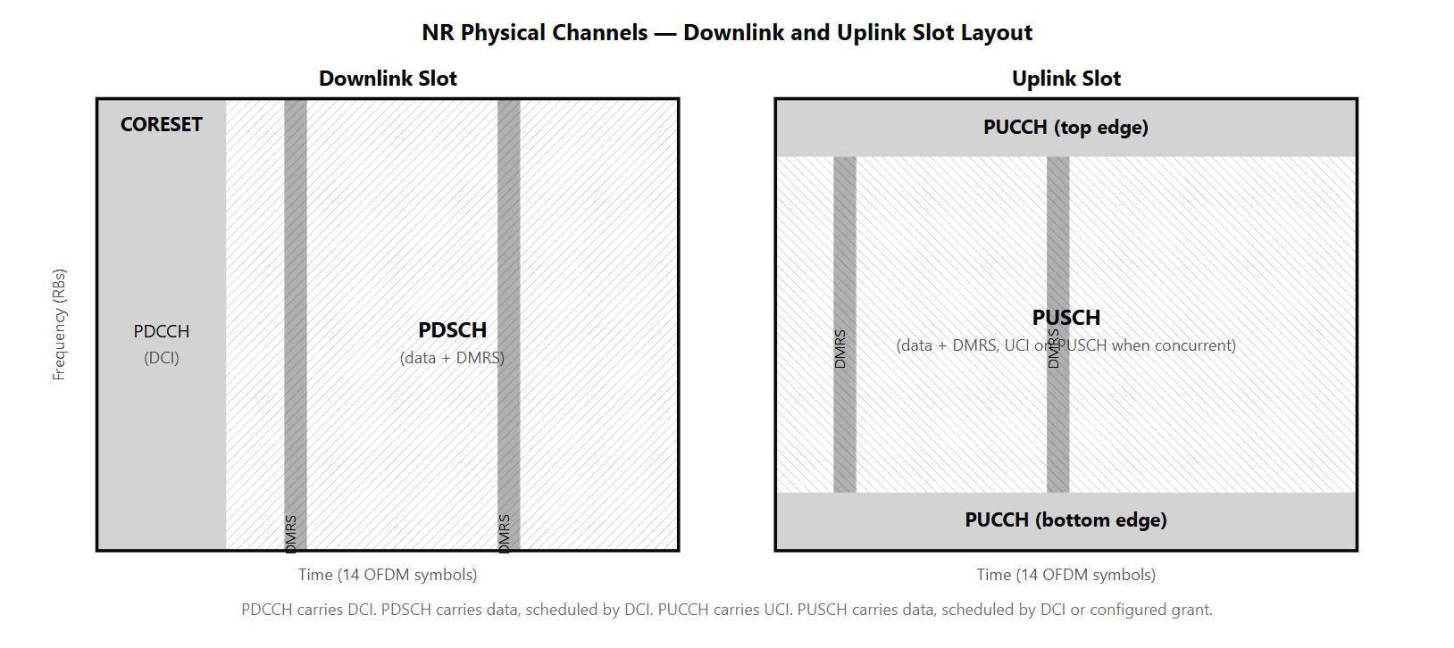
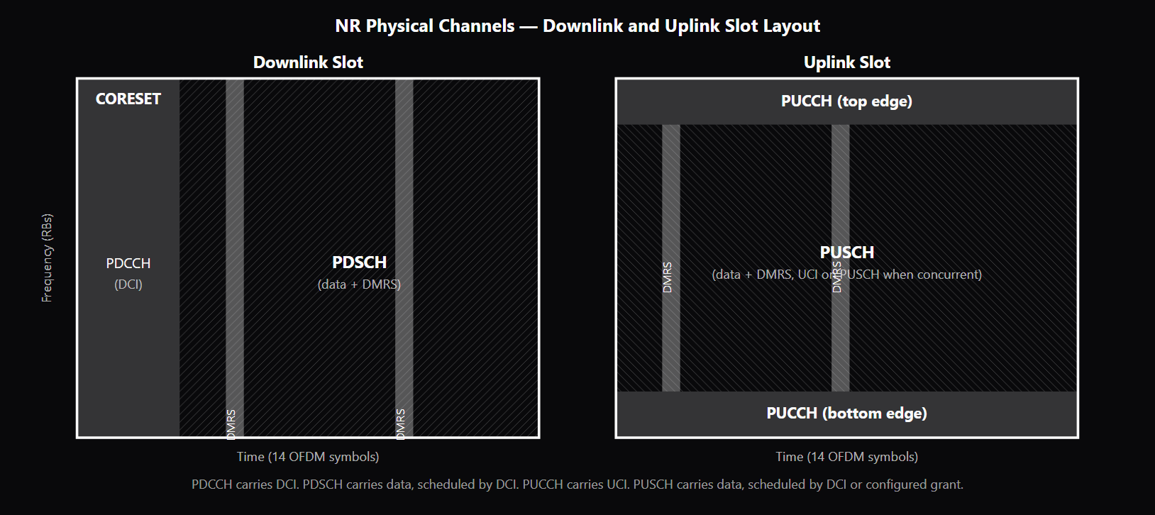
5G NR's physical-layer transmission rests on four main channels — PDCCH, PDSCH, PUCCH, PUSCH — plus the SSB used for initial access and the PRACH used for random access. Understanding what each channel carries, how it is scheduled, and how the channels relate to each other is the foundation that every other 5G modem topic rests on. Interviewers use this layer to test whether a candidate has a working mental model of the air interface or only flash-card knowledge of channel names. PDCCH (Physical Downlink Control Channel) carries DCI — Downlink Control Information. DCI carries scheduling decisions for both uplink and downlink, plus a few group-common signals (slot-format indication, preemption indication, TPC commands). PDCCH is transmitted in a CORESET (Control Resource Set), a configured time-frequency region the UE monitors. CORESET-0 is the bootstrap CORESET signaled in the MIB and used during initial access to schedule SIB1; UE-specific CORESETs are configured via RRC for the UE's regular scheduling. Search spaces tie each CORESET to a set of PDCCH candidates and a monitoring periodicity. The UE blindly decodes each candidate, descrambling the CRC with its assigned RNTIs (C-RNTI, CS-RNTI, MCS-C-RNTI, INT-RNTI, and others) to discover which DCI is addressed to it. PDSCH (Physical Downlink Shared Channel) carries downlink user data, plus SIB transmissions, paging, and the MSG2/MSG4 messages during RACH. Dynamic PDSCH is scheduled by a PDCCH-carried DCI (SPS / semi-persistent scheduling is the exception — it delivers periodic PDSCH without a per-occasion PDCCH); the DCI specifies the resource allocation (which resource blocks in frequency, which symbols in time), the modulation and coding scheme (MCS), the HARQ process ID and redundancy version (see /topics/harq), and a long list of other parameters. NR's flexibility shows up in PDSCH scheduling: both Type-0 (resource-block-group bitmap) and Type-1 (contiguous RB) frequency allocations are supported, plus mini-slot scheduling for sub-slot durations critical to URLLC latency targets (see /topics/nr-urllc-mini-slot-preemption). PUCCH (Physical Uplink Control Channel) carries UCI — Uplink Control Information. UCI bundles HARQ-ACK feedback, scheduling requests (SR), and CSI reports. PUCCH has five formats spanning the (short, small payload) corner to the (long, large payload) corner of the design space; Format 4 multiplexes multiple UEs in the same resource via pre-DFT OCC, which is unique among PUCCH formats. PUSCH (Physical Uplink Shared Channel) carries uplink user data — and during RACH it carries MSG3. PUSCH transmissions come in two grant types: dynamic grants scheduled by an uplink DCI, and configured grants pre-configured for periodic small transmissions that cut latency. The UCI-on-PUSCH multiplexing rule is one of the design details that interviewers probe most often. When a UE has UCI to report in the same slot as a scheduled PUSCH transmission, the default behavior multiplexes the UCI onto PUSCH rather than transmitting on both PUCCH and PUSCH simultaneously. This avoids the power-split that simultaneous PUCCH+PUSCH would cost (most UEs have one power amplifier), and uses the larger PUSCH coding budget to protect the UCI bits. Simultaneous PUCCH+PUSCH is an optional UE capability for cases where power-split is not the binding constraint.
Why interviewers ask
Physical channels are the structural backbone of every 5G modem interview because every other topic — HARQ, MIMO, beam management, scheduling, link adaptation — bottoms out at "what does the DCI say" and "what does the UE transmit on PUCCH/PUSCH." A candidate who fluently distinguishes the channels and can describe how a scheduling decision flows from PDCCH to PDSCH (or PUSCH) reveals working knowledge of the protocol stack. A candidate who confuses PDCCH and PDSCH or who treats PUCCH and PUSCH as interchangeable uplink channels is signaling a basic gap. The CORESET design is probed because it is the most non-obvious piece of the PDCCH architecture. Strong candidates explain that CORESET-0 is configured in the MIB rather than SIB1 because the UE needs to find the scheduling PDCCH for SIB1 before it can decode SIB1 — a chicken-and-egg constraint that the MIB→CORESET-0 mechanism solves. Weak candidates name CORESET without explaining the bootstrap requirement. DCI format families separate fallback from configurable for a reason. Fallback DCIs (0_0 for UL, 1_0 for DL) have a fixed payload size determined only by the active BWP and are always monitored in the common search space — this is the robustness mechanism that protects the UE from loss-of-scheduling during BWP switching or RRC reconfiguration transitions. Candidates who treat all DCIs as interchangeable miss this protection layer. The UCI-on-PUSCH multiplexing rule is the most-asked detail-level question because it reveals practical familiarity with the air interface. Candidates who describe simultaneous PUCCH+PUSCH as the normal case, or who claim the UE drops one to preserve the other, have not worked at the channel-mux level. The correct answer — multiplex UCI onto PUSCH by default, simultaneous PUCCH+PUSCH only as an optional UE capability — is one of those small facts that distinguishes serious candidates. RNTI fluency is probed because the RNTI is how DCI addressing works. A UE has many RNTIs at once (C-RNTI, CS-RNTI for configured scheduling, MCS-C-RNTI for an alternate MCS table, INT-RNTI for preemption, SP-CSI-RNTI for semi-persistent CSI) and must blindly descramble PDCCH CRCs with all of them to find DCIs addressed to it. Candidates who know only C-RNTI miss the broader addressing landscape.
Common mistakes
The most common mistake is treating PDCCH and PDSCH as parallel channels that "just happen" to carry control and data. They are tightly coupled — every PDSCH transmission is scheduled by a PDCCH-carried DCI, and the DCI is the link between them. A candidate who describes PDSCH as if it could exist without PDCCH has not understood the scheduling architecture. A second gap is missing the fallback-DCI design. Candidates who describe DCI 0_0 and 0_1 as "the same thing with different numbers" miss the deliberate split: 0_0 is a fixed-payload-size fallback DCI for robustness during configuration transitions, 0_1 is the configurable DCI for normal scheduling. The fallback DCIs are always monitored in the common search space precisely so the UE never loses scheduling visibility during BWP switching or reconfiguration (see /topics/nr-bwp-and-numerology). Candidates without this distinction in their mental model are missing a key robustness layer. A third gap is collapsing the PUCCH format options. NR defines five PUCCH formats spanning short/long and small/large payload combinations, and operators select the format per UE per UCI report based on payload size and link budget. Candidates who treat "PUCCH" as a single channel without naming formats miss the operational tuning surface that real deployments live and die on. A fourth gap is missing the UCI-on-PUSCH multiplexing default. Candidates who describe simultaneous PUCCH+PUSCH as the normal case, who claim the UE drops UCI when PUSCH is scheduled, or who treat UCI and PUSCH as strictly separate channels have not worked at the multiplexing layer. The correct mental model is: UCI on PUSCH is the default when they overlap, simultaneous PUCCH+PUSCH is an optional capability for specific UEs. A fifth gap is RNTI scope confusion. A candidate who names only C-RNTI without knowing that the UE simultaneously listens for CS-RNTI (configured scheduling), MCS-C-RNTI (alternate MCS table for URLLC), INT-RNTI (preemption indication), or P-RNTI (paging while in RRC_CONNECTED for paging-other-cell scenarios) reveals a narrow exposure to the actual DCI addressing surface.
5G NR Physical Channels — Role, Direction, and What They Carry
| Channel | Direction | Carries | Scheduled by | Reference Signals | Where in Slot |
|---|---|---|---|---|---|
| PDCCH | Downlink | DCI (scheduling decisions, group-common signals) | Self (CORESET monitoring) | DMRS for PDCCH (CORESET-specific) | CORESET region (typically symbols 0–2) |
| PDSCH | Downlink | Downlink user data, SIB, paging, MSG2/MSG4 | PDCCH (DCI 1_0 / 1_1 / 1_2) | DMRS for PDSCH; optional PTRS | Configurable symbols within the slot (mini-slot or full slot) |
| PUCCH | Uplink | UCI (HARQ-ACK, SR, CSI reports) | Configured (semi-static) | DMRS for PUCCH (format-specific) | Short (1–2 symbols) or long (4–14 symbols) format |
| PUSCH | Uplink | Uplink user data, MSG3, optionally UCI multiplexed in | PDCCH dynamic grant or configured grant | DMRS for PUSCH; optional PTRS | Configurable symbols within the slot |
Sample interview questions
- Why is CORESET-0 configured in the MIB rather than in SIB1?
- A. CORESET-0 is larger than SIB1, so it makes more sense to put the smaller one (CORESET-0 config) in the MIB.
- B. CORESET-0 only exists in FR2 deployments; SIB1 only exists in FR1, so they cannot share a config message.
- C. CORESET-0 and SIB1 are unrelated; CORESET-0 is for paging, SIB1 is for system information.
- D. The PDCCH monitored in CORESET-0 schedules SIB1, so the UE has to know where to look for the SIB1-scheduling PDCCH before it can decode SIB1. The MIB is the only structure available pre-SIB1, so the CORESET-0 configuration is signaled there. ✓
Option D is correct. CORESET-0 (Control Resource Set 0) is the search space the UE monitors to find the PDCCH that schedules SIB1 on PDSCH. The UE cannot decode SIB1 until it knows where the scheduling PDCCH lives, so the CORESET-0 configuration must come from a structure the UE has already decoded — and the only such structure during initial access is the MIB. The MIB carries a compact 4-bit index into a predefined table of CORESET-0 configurations, plus a 4-bit Type-0 search-space configuration. The UE reads both, derives the CORESET-0 location, and starts monitoring for the SIB1 scheduling PDCCH. Option A reverses the logic — neither is "larger" in the relevant sense; the constraint is ordering, not size. Option B is wrong; both FR1 and FR2 use CORESET-0 and SIB1. Option C is wrong; CORESET-0 is specifically used to schedule SIB1 (and other initial-access PDCCH), not for paging in a general sense. Production reality: cells that misconfigure CORESET-0 in the MIB are unreachable — UEs lock to the SSB, decode the MIB, look for SIB1 at the configured CORESET-0, find nothing, and time out. RAN-vendor RACH-debug tooling almost always includes a "MIB→CORESET-0→Type-0 PDCCH→SIB1" trace as the first thing to check.
- A UE has both a small UCI report (HARQ-ACK only, 1 bit) and a scheduled PUSCH transmission in the same slot. What happens, and why?
- A. The UE multiplexes the UCI onto PUSCH (piggybacks it on the PUSCH transmission instead of sending it separately on PUCCH). This conserves uplink resources, avoids simultaneous PUCCH+PUSCH transmissions in the same slot, and is the default behavior when UCI and PUSCH overlap in time and the multiplexing timeline conditions are met. ✓
- B. The UE drops the UCI to avoid interfering with PUSCH.
- C. The UE transmits UCI on PUCCH and PUSCH simultaneously using different antenna ports.
- D. The UE drops the PUSCH to preserve the UCI report.
Option A is correct. NR allows simultaneous PUCCH+PUSCH transmission as an optional UE capability, but the default and most common behavior is to multiplex the UCI onto the PUSCH transmission — referred to as "UCI on PUSCH." The UE inserts the UCI bits into the PUSCH resource using a specified resource-mapping rule (the UCI occupies symbol positions selected to minimize impact on the data payload's channel estimation), and the gNB knows from the DCI that scheduled the PUSCH that UCI will be embedded. Why this design: the UE only has one power amplifier in most form factors, so simultaneous PUCCH+PUSCH is a power-split that costs link budget on both. Multiplexing UCI onto PUSCH avoids the power split and uses the larger PUSCH channel-coding budget to protect the UCI bits, which is usually better than the small PUCCH format. Option B is wrong: UCI is generally too important to drop (HARQ-ACK in particular drives the link adaptation loop). Option C is technically allowed as an optional UE capability but not the default; most UEs do not advertise simultaneous PUCCH+PUSCH. Option D would hurt data throughput unnecessarily. Production reality: HARQ-ACK on PUSCH is the most common UCI-on-PUSCH case. CSI reports can also land on PUSCH when scheduled. Operators rarely disable this multiplexing because the alternative (simultaneous PUCCH+PUSCH) costs uplink coverage at cell edge.
- A UE monitors a PDCCH search space configured for DCI format 0_0 and DCI format 0_1. The two formats schedule the same channel (PUSCH). What is the practical reason to support both?
- A. DCI 0_0 and 0_1 are identical formats; supporting both is a backward-compatibility relic from LTE.
- B. DCI 0_0 is a fallback DCI: small fixed payload, scheduling on the active BWP with default parameters, designed for robustness when the UE may not yet have full configuration. DCI 0_1 is the feature-rich DCI: variable size based on BWP and feature configuration, supports MIMO layers, frequency-hopping, configured-grant adjustments, and the full set of NR features. The fallback DCI is used during transitions (e.g., right after BWP switch, before full reconfiguration is applied) and as a small-fixed-size option in low-overhead search spaces. ✓
- C. DCI 0_0 schedules PUSCH on uplink, DCI 0_1 schedules PUCCH on uplink.
- D. DCI 0_0 is used in FR1 only, DCI 0_1 is used in FR2 only.
Option B is correct. NR DCI formats come in fallback variants (0_0 for UL, 1_0 for DL) and configurable variants (0_1 for UL, 1_1 for DL, plus 0_2 and 1_2 added for URLLC). The fallback DCIs are small and have a fixed payload size that depends only on the active BWP bandwidth — this lets the UE decode the DCI even when its full configuration is in flux. The configurable DCIs have payload sizes that depend on the UE configuration (number of MIMO layers configured, frequency-hopping enabled, CSI request fields, etc.) and carry the feature-rich scheduling parameters. Why the fallback DCI matters: during BWP switching, during initial access before RRC reconfiguration, and in low-overhead search spaces (e.g., common search spaces for group-common DCIs), the gNB and UE need to agree on the DCI payload size without depending on the full UE-specific configuration. The fallback DCI gives that fixed-size anchor. Option A misses the fallback-vs-configurable design rationale. Option C is wrong; both formats schedule PUSCH. Option D is wrong; both formats are used in both FR1 and FR2. Production reality: UEs monitor for fallback DCIs in a common search space (CSS), even when their UE-specific search space (USS) carries the configurable DCIs. This is a robustness feature that prevents UE loss-of-scheduling during reconfiguration transitions.
Frequently asked questions
- What are the NR physical channels?
- NR defines four primary physical channels plus the SSB. PDCCH (Physical Downlink Control Channel) carries scheduling decisions (DCI) and a few group-common signals; PDSCH (Physical Downlink Shared Channel) carries downlink data scheduled by PDCCH. PUCCH (Physical Uplink Control Channel) carries small uplink control information (HARQ-ACK, scheduling requests, CSI reports); PUSCH (Physical Uplink Shared Channel) carries uplink data scheduled by an uplink DCI. The SSB carries synchronization signals and the MIB, used during initial access (see /topics/nr-initial-access-ssb-rach). PBCH is part of the SSB. PRACH (Physical Random Access Channel) carries RACH preambles. Reference signals (DMRS, CSI-RS, SRS, PTRS) sit alongside these channels on the resource grid (see /topics/nr-reference-signals).
- What are PDCCH and CORESET?
- PDCCH is the downlink control channel that carries DCI (Downlink Control Information) — scheduling decisions for both uplink and downlink. The PDCCH is transmitted in a CORESET (Control Resource Set), which is a configured time-frequency region the UE monitors for PDCCH transmissions. CORESETs are typically 1–3 OFDM symbols at the start of a slot (the "control region") spanning a configured set of resource blocks. A search space is a configuration that ties a CORESET to a set of PDCCH candidates and a monitoring periodicity. CORESET-0 is the bootstrap CORESET signaled in the MIB and used to find SIB1 during initial access. UE-specific CORESETs are configured later via RRC for the UE's regular scheduling.
- How is PDSCH allocated to a UE?
- When the gNB has downlink data for a UE, it transmits a DCI on PDCCH addressed to the UE's C-RNTI (or a temporary C-RNTI during initial access). The DCI carries the PDSCH scheduling: which resource blocks in frequency, which symbols in time within the slot, the modulation and coding scheme (MCS), the redundancy version for HARQ, the HARQ process ID, and other parameters. The UE decodes the DCI, then attempts to decode PDSCH on the indicated resources. PDSCH resource allocation in NR is more flexible than LTE — both Type-0 (RBG bitmap) and Type-1 (contiguous-RB) frequency allocations exist, plus mini-slot scheduling for sub-slot durations. PDSCH carries DMRS and optionally PTRS for channel estimation (see /topics/nr-reference-signals).
- What are the PUCCH formats and when is each used?
- NR defines five PUCCH formats. Format 0 is a short PUCCH (1–2 symbols) carrying up to 2 bits, used for small HARQ-ACK and SR. Format 1 is a long PUCCH (4–14 symbols) carrying up to 2 bits, used when more time-domain redundancy is needed at the cell edge. Format 2 is short (1–2 symbols) carrying more than 2 bits, used for small CSI reports. Format 3 and Format 4 are long PUCCH formats carrying more than 2 bits, used for larger payloads — Format 4 multiplexes multiple UEs in the same resource via pre-DFT OCC, Format 3 is single-UE. Operators tune PUCCH-format selection per UE based on the UCI payload size and the link budget; cell-edge UEs are typically pushed to long formats for the time-domain processing gain.
- What are the PUSCH grant types?
- PUSCH transmissions come in two grant types. Dynamic grants are scheduled by an uplink DCI (format 0_0 or 0_1) on PDCCH — the gNB sees the UE has uplink data (via a BSR), issues a grant, and the UE transmits PUSCH on the indicated resources. Configured grants are pre-configured uplink resources that recur periodically without per-transmission PDCCH signaling — they cut the latency of small periodic uplink transmissions (URLLC, periodic CSI reporting, sensor traffic). Configured grants come in two flavors: Type-1 (fully RRC-configured) and Type-2 (RRC configures the periodic resource, then a PDCCH/DCI addressed to the CS-RNTI activates and deactivates it, with the UE returning a Configured Grant Confirmation MAC CE). PUSCH carries DMRS for channel estimation and optionally PTRS for phase tracking at high frequencies.
- What are the RNTI types in NR?
- RNTI (Radio Network Temporary Identifier) is a 16-bit identifier used to scramble the CRC of a DCI or to address a PDSCH. Common RNTIs: C-RNTI (the UE's permanent unicast identifier in a serving cell), CS-RNTI (configured scheduling for SPS PDSCH and Type-1 configured grants), RA-RNTI (temporary, used during RACH for RAR), P-RNTI (paging), SI-RNTI (system information broadcast), MCS-C-RNTI (used when a different MCS table is configured for URLLC), INT-RNTI (preemption indication), SP-CSI-RNTI (semi-persistent CSI), TC-RNTI (temporary C-RNTI assigned during RACH before contention resolution). The UE descrambles the PDCCH CRC with each RNTI it currently has and discovers which DCI is addressed to it.
- What are the DCI format families?
- NR DCI formats split into fallback (small, fixed payload size) and configurable (variable size based on UE configuration). Format 0_0 is fallback uplink (small, scheduling PUSCH on the active BWP with default parameters); 0_1 is configurable uplink (full feature set); 0_2 is the URLLC compact uplink variant. Format 1_0 is fallback downlink (small, scheduling PDSCH or carrying paging/SI grants); 1_1 is configurable downlink; 1_2 is the URLLC compact downlink. Format 2_x is group-common — 2_0 carries slot-format indication, 2_1 carries preemption indication, 2_2 carries TPC commands, 2_3 carries SRS group-trigger. The fallback DCIs are always monitored as a robustness mechanism during configuration transitions; configurable DCIs are the workhorse for normal scheduling.
- When does UCI go on PUCCH versus PUSCH?
- When the UE has UCI to report and no concurrent PUSCH, it transmits UCI on PUCCH using the configured format. When the UE has both UCI and a concurrent PUSCH grant in the same slot, the default behavior is "UCI on PUSCH" — the UCI bits are multiplexed onto the PUSCH transmission, occupying symbol positions selected to minimize impact on the data payload's channel estimation. This avoids simultaneous PUCCH+PUSCH (which costs uplink power-split for the UE's single PA in most form factors) and uses the larger PUSCH coding budget to protect the UCI bits. Simultaneous PUCCH+PUSCH is an optional UE capability supported by some devices, mainly for cases where power-split is not the binding constraint.
Related topics
Siblings
- 5G NR Explained: Numerology, BWP, HARQ, and Frame Structure
- NR Reference Signals: DMRS, CSI-RS, SRS, PTRS, and the SSB
- NR Channel Coding: LDPC, Polar, MCS, and Link Adaptation
- NR MAC Scheduling: PDCCH Allocation, BSR, DRX, Configured Grant
- NR BWP and Numerology: How Scalable Subcarrier Spacing Works
- NR Initial Access: SSB, MIB, SIB1, and the RACH Procedure
- OFDM Explained: Subcarriers, Cyclic Prefix, PAPR, and OFDMA
- HARQ (Hybrid Automatic Repeat reQuest)
- NR Beam Management: SSB Sweep, P-1/P-2/P-3, TCI States, QCL
Practice
Essential AI-Native Skills for PDCCH, PDSCH, PUCCH, PUSCH: The 5G NR Physical Channels
Modern engineering work increasingly uses AI tools for design and code review, debugging, documentation, test and testbench generation, and workflow automation. The goal is not to let AI replace engineering judgment — it is to move faster while keeping verification discipline.
- Use AI to explain unfamiliar code, logs, waveforms, datasheets, or test failures.
- Break large problems into small, reviewable steps you can verify independently.
- Ask AI for hypotheses, then validate them against tests, measurements, simulations, or lab data.
- Version-control your analysis scripts, testbenches, and configs — keep changes small and reviewable.
- Document your assumptions, design tradeoffs, and debugging decisions.
- Verify AI output before trusting it: run the checks that fit the domain — unit tests, linters, simulations, or bench/lab measurements.
- Review AI output for correctness, edge cases, and real-world consequences.
PDCCH, PDSCH, PUCCH, PUSCH: The 5G NR Physical Channels — coming to the question bank
The adaptive practice engine is already live for core wireless, RF, and ML systems. PDCCH, PDSCH, PUCCH, PUSCH: The 5G NR Physical Channels isn't covered in the question bank yet — get notified when it's added.