NR BWP and Numerology: How Scalable Subcarrier Spacing Works Interview Prep
5G NR BWP and numerology — subcarrier spacing μ=0..4, FR1 vs FR2, frame/slot structure, resource grid, BWP switching, and CP overhead.
Quick answer
NR's scalable numerology is the design that lets one technology framework serve everything from large sub-6 GHz outdoor cells to small mmWave indoor cells.
Numerology and BWP are foundational concepts in NR — they show up in nearly every other topic (initial access depends on the SSB numerology configured for the carrier, beam management timing depends on slot duration, MAC scheduling decisions depend on RB counts, HARQ timing depends on slot duration, and so on).
Editorial review
Written by
CompoundLearn editorial team
Wireless / RF / hardware engineering
Reviewed by
CompoundLearn editorial team
Wireless / RF / hardware engineering
Last reviewed
Built from curated topic maps, editorial validation, and subject-matter review so the page stays aligned with the interview intent and the current content pipeline.
What it is
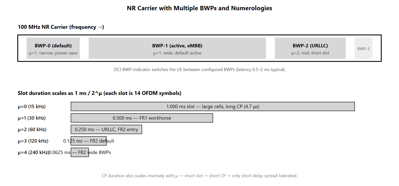
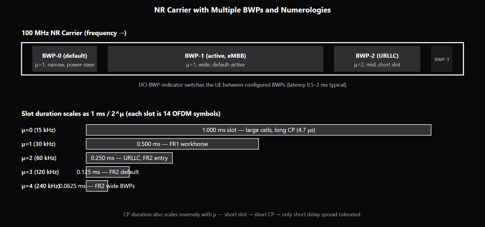
NR's scalable numerology is the design that lets one technology framework serve everything from large sub-6 GHz outdoor cells to small mmWave indoor cells. Subcarrier spacing (SCS) is parameterized as SCS = 15·2^μ kHz where μ ranges from 0 to 4, giving SCS values of 15, 30, 60, 120, and 240 kHz. OFDM symbol duration scales inversely with SCS, slot duration scales as 1 ms / 2^μ, and the cyclic-prefix duration scales proportionally with the symbol duration to keep CP overhead roughly constant. The numerology choice is fundamentally a coverage-versus-latency trade-off: low μ gives long CP (handles long delay spread, supports large cells) and long slot duration (longer HARQ round-trip); high μ gives short CP (works only at short delay spread) and short slot duration (fast HARQ, low latency). The frequency range mapping reflects this trade-off. FR1 (sub-7.125 GHz) typically uses μ=0, 1, 2 with μ=1 (30 kHz) as the workhorse for new NR deployments and μ=0 (15 kHz) reserved for LTE-compatible deployments. FR2 (24.25–52.6 GHz) typically uses μ=2, 3, 4 with μ=3 (120 kHz) as the default. Above 52.6 GHz (FR2-2 in Rel-17) the range extends and higher μ values appear. The pairing is driven by physical-layer realities: at higher carrier frequencies the channel delay spread is shorter (smaller cells, less scatterer count), and phase noise per Hz drops with shorter symbol duration, both favoring high μ. A bandwidth part (BWP) is a contiguous frequency portion of an NR carrier configured with its own numerology. A UE can be configured with up to four DL BWPs and four UL BWPs per serving cell, with one DL (and one UL) BWP active at any time. The others are configured-but-inactive — preserved for future activation. BWPs enable two important capabilities: power saving (operating on a narrow BWP reduces UE baseband processing per slot, saving power during low-activity periods) and mixed numerology (different BWPs can carry different μ values, letting one carrier serve mixed eMBB and URLLC traffic simultaneously). BWP switching is signaled via DCI. The DCI formats 0_1 (uplink) and 1_1 (downlink) include a BWP-indicator field. When the UE decodes a DCI with a different BWP-indicator than its current active BWP, it switches — stopping monitoring on the current BWP, retuning its receive chain, and beginning monitoring on the new BWP. Switching latency depends on UE capability (typical 0.5–2 ms for intra-carrier switches), and the gNB must respect this latency in its scheduling. The BWP-InactivityTimer provides a safety fallback that auto-returns the UE to the default BWP after a configured inactivity period. The resource grid is the time-frequency lattice of resource elements (REs) that NR scheduling operates on. One RE is one subcarrier × one OFDM symbol. A resource block (RB) is always 12 contiguous subcarriers in frequency, but the RB bandwidth depends on numerology: 180 kHz at μ=0, 360 kHz at μ=1, 720 kHz at μ=2, etc. The total number of RBs in a BWP depends on the BWP bandwidth and the numerology; at μ=1, a 100 MHz BWP holds about 273 RBs. The resource grid is the substrate that PDSCH/PUSCH resource allocations sit on, with DCI signaling (start RB, number of RBs, start symbol, number of symbols) for each scheduled transmission.
Why interviewers ask
Numerology and BWP are foundational concepts in NR — they show up in nearly every other topic (initial access depends on the SSB numerology configured for the carrier, beam management timing depends on slot duration, MAC scheduling decisions depend on RB counts, HARQ timing depends on slot duration, and so on). A candidate who fluently navigates numerology, slot timing, RB counts, and BWP switching reveals a working mental model of the air interface. A candidate who struggles to relate SCS to slot duration or to explain when BWP switching happens has not yet internalized the layered timing structure NR depends on. The numerology-to-coverage trade-off is the most-asked design-rationale question. Strong candidates explain that low μ gives long CP for large cells with high delay spread, while high μ gives short slot duration for low latency in small cells. Weak candidates know the formula SCS = 15·2^μ kHz but cannot describe why each μ is paired with a deployment scenario. The CP overhead question (does CP overhead change with μ?) is the diagnostic test — the correct answer is that CP duration scales proportionally so the ratio stays roughly constant, but the absolute CP duration shrinks, which is the binding constraint at high μ. BWP switching via DCI is probed because the LTE comparison is wrong. In LTE, the carrier bandwidth is fixed at network configuration; the UE always operates on the full carrier. NR added BWP specifically to support power saving (narrow BWP during low activity, wide BWP during bursts) and mixed numerology (μ=1 BWP for eMBB plus μ=2 BWP for URLLC on the same carrier). Candidates who describe NR as if it operated on a fixed-bandwidth carrier (or who claim BWP switching requires RRC reconfiguration rather than DCI) reveal a gap in their NR understanding. Mixed numerology on one carrier is a frequent advanced-question. Strong candidates can describe a scenario — say, μ=1 BWP-1 for eMBB and μ=2 BWP-2 for URLLC on a 100 MHz carrier — and explain that they sit on separate BWPs to avoid inter-numerology interference. Weak candidates claim only one numerology can exist on a carrier (LTE-think) or claim the two numerologies can share REs (which would cause interference).
Common mistakes
The most common mistake is treating slot duration as fixed at 1 ms. NR slot duration scales as 1 ms / 2^μ, so the slot at μ=3 is 0.125 ms — eight times shorter than at μ=0. Candidates who assume slot is always 1 ms (LTE-think) miss the entire latency lever NR introduced. A second gap is confusing slot duration with subframe duration. NR keeps the 1 ms subframe (for backward-compatibility timing references and for SFN signaling) but the slot is the new scheduling unit and depends on μ. Candidates who use slot and subframe interchangeably have not internalized the new structure. A third gap is missing the BWP power-saving rationale. Operating on a narrow BWP reduces the UE's baseband processing per slot — smaller IFFT/FFT, fewer REs to demodulate, less RX power. The default-BWP fallback mechanism specifically targets this: when the UE has no scheduling activity, it falls back to the narrow default BWP. Candidates who describe BWP only as a frequency-domain partitioning miss the power-saving angle that is one of the main motivations. A fourth gap is missing the BWP-and-numerology cross-product. Each BWP carries its own numerology, so when a UE switches BWPs, it also switches numerology if the BWPs are configured with different μ values. This is the mechanism that supports mixed eMBB+URLLC deployments on one carrier — eMBB UEs sit on a μ=1 BWP, URLLC UEs switch to a μ=2 BWP when latency-sensitive bursts arrive. Candidates who describe BWPs as same-numerology partitions miss the multi-numerology design. A fifth gap is confusing μ with channel BW. μ controls SCS and (with the RB count) the BWP bandwidth, but the carrier bandwidth itself is set by the operator deployment choice. A 100 MHz carrier at FR1 supports μ=1 and μ=2 (30 and 60 kHz) with different RB counts — 15 kHz (μ=0) tops out at 50 MHz per TS 38.104, so it is not valid at 100 MHz; among the valid options the operator picks which μ to use based on the deployment scenario. Candidates who tie μ directly to channel BW are missing the configurable layer. See /topics/ofdm for the OFDM fundamentals that NR's scalable numerology builds on.
NR Numerology — μ Values and Slot Properties
| μ | SCS (kHz) | Slot Duration | Symbol Duration | Normal CP (μs) | Typical Frequency Range | Use Case |
|---|---|---|---|---|---|---|
| 0 | 15 | 1 ms | ~66.7 μs | ~4.7 | FR1 sub-3 GHz | Large cells, long delay spread, LTE-compatible |
| 1 | 30 | 0.5 ms | ~33.3 μs | ~2.3 | FR1 mid-band (3–7 GHz) | Workhorse FR1 numerology for NR |
| 2 | 60 | 0.25 ms | ~16.7 μs | ~1.2 | FR1 wide bands, FR2 low | Higher-bandwidth FR1, URLLC, FR2 entry |
| 3 | 120 | 0.125 ms | ~8.3 μs | ~0.6 | FR2 typical | Default mmWave numerology |
| 4 | 240 | 0.0625 ms | ~4.2 μs | ~0.3 | FR2 wide BWPs | Very wide mmWave BWPs, narrow delay spread only |
Sample interview questions
- How does the cyclic-prefix (CP) overhead change as the NR subcarrier spacing index μ increases, and why does this constrain the choice of μ for a given deployment?
- A. CP overhead stays constant across μ because the CP is always set to a fixed time duration.
- B. CP overhead doubles each step in μ because the symbol shrinks but the CP stays the same.
- C. CP duration scales inversely with μ (CP shrinks as SCS grows), so the CP-to-symbol-duration ratio stays approximately the same. However, the absolute CP duration shrinks — at μ=4 (240 kHz SCS) the CP is short enough that only short-delay-spread channels work. This is why large cells use lower μ (longer CP tolerates more multipath) and FR2 small cells use higher μ (short CP is fine for the short delay spread typical at mmWave). ✓
- D. CP overhead is always 25% regardless of μ.
Option C is correct. NR uses scalable numerology with SCS = 15·2^μ kHz, so μ=0 gives 15 kHz, μ=1 gives 30 kHz, μ=2 gives 60 kHz, μ=3 gives 120 kHz, μ=4 gives 240 kHz. The OFDM symbol duration is inversely proportional to SCS, so symbols also shrink by 2^μ. The CP is configured to be a roughly fixed fraction of the symbol duration (≈7% for normal CP), so it shrinks proportionally — the CP-to-symbol ratio is approximately preserved. The constraint is the absolute CP duration. CP must be longer than the channel's delay spread to absorb multipath without inter-symbol interference. At μ=0 (15 kHz, used in low-band FR1) the CP is about 4.7 μs — long enough for the multipath delay spread of large cells with significant scatterer-induced delay. At μ=4 (240 kHz, FR2-only) the CP is about 0.3 μs — only useful when the delay spread is short, which is typical for small mmWave cells with limited scatterer count. This is the design principle behind the (deployment scenario, μ) pairing: large outdoor cells with high delay spread need low μ; FR2 small cells with short delay spread can use high μ to shrink slot duration and reduce latency. Option A is wrong — CP duration scales with the symbol duration, not fixed. Option B inverts the ratio. Option D is a number that does not correspond to either normal-CP or extended-CP fractions. Production reality: μ selection is a coverage-vs-latency trade-off, not a free parameter; operators pick μ per band and deployment scenario.
- A UE has four BWPs configured by RRC, with BWP-0 as the initial BWP and BWP-1 as the active BWP. The UE receives a DCI with the BWP-indicator field pointing to BWP-2. What happens, and what is the latency cost?
- A. The UE ignores the BWP-indicator until the next RRC reconfiguration.
- B. The UE switches BWP only if explicitly granted by an RRC reconfiguration message; DCI cannot trigger BWP switching.
- C. The UE switches BWP within one slot with no measurable latency cost.
- D. The UE performs BWP switching: it stops monitoring on BWP-1, retunes its baseband (and RF if BWP-2 spans a different RF region), and starts monitoring on BWP-2. The switching latency depends on UE capability (typical values: 0.5–2 ms for intra-frequency switches within the same carrier; longer if RF retuning is required). During the switch the UE cannot decode PDCCH, so the gNB must respect a configured BWP-InactivityTimer or schedule with appropriate gap. ✓
Option D is correct. NR allows dynamic BWP switching via DCI — the DCI 1_1 (downlink) and 0_1 (uplink) include a BWP-indicator field that picks one of up to four configured BWPs. The UE on receiving a BWP switch decoded in DCI: stops monitoring on the current BWP, retunes the receive chain to the indicated BWP's frequency-domain position and numerology, and starts monitoring on the new BWP. The switch delay is a UE-capability parameter (TS 38.133 defines BWP-switch-delay Type 1 and Type 2 in slots, numerology-dependent — for example a few slots, on the order of sub-millisecond to a couple of milliseconds); a UE advertising the faster Type 1 delay completes the switch sooner than a Type 2 UE. Why this matters: BWP switching is the mechanism that lets the UE operate on a narrow BWP for power savings (smaller BWP = less baseband processing per slot = lower power) and switch to a wide BWP for high-throughput bursts. The DCI-driven switch is also the mechanism for switching numerology — e.g., from a μ=1 BWP for typical traffic to a μ=2 BWP for URLLC. The BWP-InactivityTimer (configured at RRC) is the safety mechanism: if no scheduled activity occurs on the active BWP for the timer duration, the UE auto-falls-back to the default BWP. This prevents the UE from being stranded on a BWP the gNB has stopped scheduling. Option A misses that DCI can trigger BWP switching. Option B is the LTE model; NR specifically added DCI-driven BWP switching for power-saving and dynamic numerology selection. Option C is too optimistic — the switch has a measurable cost and the gNB must respect it. Production reality: UEs frequently switch between a narrow default BWP and a wider BWP as traffic ramps up and down; the switching latency is one of the parameters operators tune for low-power deployments.
- A 100 MHz NR carrier at FR1 supports both μ=1 (30 kHz SCS) and μ=2 (60 kHz SCS) BWPs. What is the slot duration at each numerology, and why might the network configure multiple numerologies on the same carrier?
- A. Slot duration scales as 1 ms / 2^μ: μ=1 → 0.5 ms, μ=2 → 0.25 ms (each slot is 14 OFDM symbols). The network configures multiple numerologies to serve different service requirements simultaneously: μ=1 for typical eMBB traffic (good coverage, balanced overhead), μ=2 for latency-sensitive URLLC services (shorter slot → lower latency → faster HARQ feedback round-trip). Different numerologies operate on separate BWPs to avoid inter-numerology interference on the same time-frequency resource. ✓
- B. Slot duration is always 1 ms regardless of μ.
- C. Slot duration is fixed at 0.5 ms for FR1 and 0.125 ms for FR2 regardless of μ.
- D. The network cannot configure multiple numerologies on the same carrier.
Option A is correct. NR slot duration scales with μ: slot duration = 1 ms / 2^μ. So μ=0 → 1 ms slot, μ=1 → 0.5 ms slot, μ=2 → 0.25 ms slot, μ=3 → 0.125 ms, μ=4 → 0.0625 ms. Each slot contains 14 OFDM symbols (regardless of μ); what shrinks is the symbol duration. Configuring multiple numerologies on the same carrier serves the mixed-service deployment scenario: eMBB traffic benefits from μ=1 (long enough slot for HARQ to amortize over typical traffic, good coverage from longer CP), while URLLC services need μ=2 or higher (short slot → fast HARQ feedback → low end-to-end latency). The two coexist on separate BWPs within the same carrier. BWP-1 might be the μ=1 eMBB BWP; BWP-2 might be the μ=2 URLLC BWP. The UE switches between them via DCI as service needs change, or two UEs operate simultaneously on the two BWPs. Mini-slot scheduling within μ=1 also supports URLLC by allowing 2/4/7-symbol scheduling units within the slot, but this is in addition to numerology-based latency reduction, not in place of it. Option B confuses slot duration with subframe duration. Option C is wrong; slot duration depends on μ, not just frequency range. Option D is wrong; multi-numerology on one carrier is a deliberate NR design. Production reality: mixed-numerology deployments are common in URLLC-capable networks; operators tune the μ assignments per BWP based on the service mix.
Frequently asked questions
- What is NR numerology?
- Numerology in NR is the parameterized framework that defines subcarrier spacing (SCS), symbol duration, slot duration, and CP length. NR defines numerology values μ from 0 to 4 with SCS = 15·2^μ kHz: μ=0 gives 15 kHz (matches LTE), μ=1 gives 30 kHz, μ=2 gives 60 kHz, μ=3 gives 120 kHz, μ=4 gives 240 kHz. The OFDM symbol duration scales inversely with SCS, and slot duration scales as 1 ms / 2^μ. Each slot has 14 OFDM symbols with normal CP (12 with extended CP, which is only defined for μ=2 / 60 kHz). NR can carry multiple numerologies on the same carrier through BWP configuration — different BWPs can have different μ values, letting one carrier serve mixed eMBB and URLLC traffic.
- What is a BWP (Bandwidth Part)?
- A BWP is a contiguous frequency portion of an NR carrier with its own numerology configuration. A UE can be configured with up to four DL BWPs and four UL BWPs per serving cell, with one DL (and one UL) BWP active at any time. Active BWP determines where the UE monitors PDCCH and where uplink and downlink scheduling happens; the inactive BWPs are configured-but-unused (saved for future activation). BWPs enable two important capabilities: power-saving (UE operates on a narrow BWP to reduce baseband processing) and mixed numerology (different BWPs can have different SCS for different services). BWP switching is triggered by DCI with a BWP-indicator field, with switching latency dependent on UE capability.
- What are FR1 and FR2?
- NR defines two frequency ranges. FR1 spans roughly 410 MHz–7.125 GHz and uses numerologies μ=0, 1, 2 (15, 30, 60 kHz SCS), with 60 kHz typically reserved for the wider FR1 bands. FR2 spans roughly 24.25–52.6 GHz and uses numerologies μ=2, 3, 4 (60, 120, 240 kHz SCS) — though deployments above 52.6 GHz (FR2-2) extend the range and add μ=5/6 for very wide bands. FR1 is the sub-6 GHz "coverage band" used for broad mobile coverage; FR2 is the mmWave "capacity band" used for short-range high-throughput links. The numerology choice ties to frequency range because phase noise, delay spread, and Doppler all scale with carrier frequency, and the SCS must be selected to match.
- How does the NR slot structure work?
- Each NR slot is 14 OFDM symbols regardless of numerology — what shrinks with higher μ is the per-symbol duration. Slot duration is therefore 1 ms at μ=0, 0.5 ms at μ=1, 0.25 ms at μ=2, 0.125 ms at μ=3. Within a slot, symbols can be allocated to downlink, uplink, or flexible directions; the slot format is signaled either statically by RRC, dynamically by the Slot Format Indicator (SFI) in DCI 2_0, or implicitly by the scheduling DCI. NR also supports mini-slot scheduling — 2, 4, or 7 symbols within a slot — which is the latency-reduction mechanism for URLLC services on top of the μ-based latency reduction.
- What is the resource grid in NR?
- The NR resource grid is the time-frequency lattice of resource elements (REs). One RE is one subcarrier in frequency × one OFDM symbol in time. A resource block (RB) is 12 contiguous subcarriers in frequency (always 12, regardless of numerology). The total number of RBs in a BWP depends on the BWP bandwidth and the numerology: at μ=1 (30 kHz SCS), each RB is 360 kHz wide, so a 100 MHz BWP holds about 273 RBs. The resource grid is the structure that PDSCH/PUSCH resource allocations sit on, with DCI signaling the (start RB, number of RBs, start symbol, number of symbols) for each scheduled transmission.
- How does BWP switching work?
- BWP switching is signaled via DCI. The DCI formats 0_1 (uplink) and 1_1 (downlink) include a BWP-indicator field that selects one of the configured BWPs as the new active BWP. When the UE decodes a DCI with a different BWP-indicator than the current active BWP, it switches: stops monitoring on the current BWP, retunes its receive chain, and begins monitoring on the new BWP. Switching latency depends on UE capability (typical 0.5–2 ms for intra-carrier). A BWP-InactivityTimer at RRC provides a safety fallback — if no scheduling activity occurs for the configured duration, the UE falls back to the default BWP automatically, preventing strand-on-inactive-BWP scenarios.
- Why does NR support scalable numerology?
- Scalable numerology lets NR serve very different deployment scenarios with one technology framework. Low-μ numerologies (15 kHz) suit large outdoor cells where channel delay spread is high and CP must be long — they match LTE-style sub-6 GHz coverage. Mid-μ (30, 60 kHz) suit dense urban FR1 deployments with shorter delay spread and tighter latency targets. High-μ (120, 240 kHz) suit mmWave (FR2) where delay spread is short, phase noise per Hz drops with shorter symbol duration, and small slot duration enables low latency. Without scalable numerology, NR would either need to repeat LTE's 15 kHz everywhere (poor latency at mmWave, no PHY-level latency lever) or commit to high SCS everywhere (broken coverage in large cells). The scaling is the design that lets one PHY serve from low-band coverage to mmWave capacity.
- How is CP overhead related to numerology?
- CP duration in NR scales inversely with SCS — normal CP is configured as approximately 7% of the symbol duration, so the CP shrinks proportionally as μ increases. The absolute CP duration is therefore: μ=0 → 4.7 μs, μ=1 → 2.3 μs, μ=2 → 1.2 μs, μ=3 → 0.6 μs, μ=4 → 0.3 μs. The CP must be longer than the channel delay spread to absorb multipath, so deployment scenarios with long delay spread require low μ. A 1 km outdoor cell with 2 μs delay spread is fine at μ=0 (4.7 μs CP) but would have ISI at μ=2 (1.2 μs CP). FR2 small cells typically have sub-microsecond delay spread, so high μ is fine. NR also supports an extended CP option at μ=2 (60 kHz SCS) for specific use cases where longer CP is needed at that numerology.
Related topics
Siblings
- 5G NR Explained: Numerology, BWP, HARQ, and Frame Structure
- PDCCH, PDSCH, PUCCH, PUSCH: The 5G NR Physical Channels
- NR MAC Scheduling: PDCCH Allocation, BSR, DRX, Configured Grant
- OFDM Explained: Subcarriers, Cyclic Prefix, PAPR, and OFDMA
- URLLC in 5G NR: Mini-Slots, Preemption, and Sub-1ms Latency
- NR Reference Signals: DMRS, CSI-RS, SRS, PTRS, and the SSB
- LTE-Advanced
Practice
Essential AI-Native Skills for NR BWP and Numerology: How Scalable Subcarrier Spacing Works
Modern engineering work increasingly uses AI tools for design and code review, debugging, documentation, test and testbench generation, and workflow automation. The goal is not to let AI replace engineering judgment — it is to move faster while keeping verification discipline.
- Use AI to explain unfamiliar code, logs, waveforms, datasheets, or test failures.
- Break large problems into small, reviewable steps you can verify independently.
- Ask AI for hypotheses, then validate them against tests, measurements, simulations, or lab data.
- Version-control your analysis scripts, testbenches, and configs — keep changes small and reviewable.
- Document your assumptions, design tradeoffs, and debugging decisions.
- Verify AI output before trusting it: run the checks that fit the domain — unit tests, linters, simulations, or bench/lab measurements.
- Review AI output for correctness, edge cases, and real-world consequences.
NR BWP and Numerology: How Scalable Subcarrier Spacing Works — coming to the question bank
The adaptive practice engine is already live for core wireless, RF, and ML systems. NR BWP and Numerology: How Scalable Subcarrier Spacing Works isn't covered in the question bank yet — get notified when it's added.