OFDM Explained: Subcarriers, Cyclic Prefix, PAPR, and OFDMA Interview Prep
OFDM interview prep for wireless and RF engineers: subcarriers, cyclic prefix, PAPR, channel estimation, FFT-size tradeoffs, and OFDM vs OFDMA — with worked sample questions.
Quick answer
OFDM (Orthogonal Frequency-Division Multiplexing) is a multi-carrier modulation scheme that splits a wideband signal into hundreds or thousands of narrow, mutually orthogonal subcarriers, each carrying a low-rate QAM symbol stream.
OFDM is the fundamental "are you actually a physical-layer engineer?" benchmark.
Editorial review
Written by
CompoundLearn editorial team
Wireless / RF / hardware engineering
Reviewed by
CompoundLearn editorial team
Wireless / RF / hardware engineering
Last reviewed
Built from curated topic maps, editorial validation, and subject-matter review so the page stays aligned with the interview intent and the current content pipeline.
Key points
- A cyclic prefix at least as long as the channel delay spread turns the linear channel convolution into a circular one, so the DFT diagonalizes the channel and equalization collapses to one complex divide per subcarrier.
- OFDM makes frequency-selective MIMO tractable (see /topics/mimo): each subcarrier sees a flat, narrowband channel, so precoding, rank adaptation, and equalization happen independently per tone instead of as one wideband equalization problem.
- Carrier-frequency offset and phase noise are OFDM’s sharpest weakness: their shared component is a common phase error (CPE) that rotates every subcarrier and is correctable per symbol; the residual breaks orthogonality and becomes inter-carrier interference (ICI) — for a small carrier-frequency offset the ICI grows with the square of the normalized offset, while phase-noise ICI scales with the oscillator linewidth relative to the subcarrier spacing.
- Subcarrier spacing is a tradeoff, not a default: delay spread sets the minimum CP (and thus the maximum SCS), Doppler and phase noise set the minimum SCS to bound ICI, and narrower SCS buys spectral efficiency at the cost of frequency-offset fragility — which is why mmWave uses wide SCS (120–240 kHz).
- High PAPR (≈8–12 dB) forces power-amplifier back-off; DFT-spread OFDM (SC-FDMA) gives up some frequency-selective scheduling for ~2–4 dB lower PAPR, which is why it is the LTE PUSCH default and an NR uplink option.
- OFDM is a waveform; OFDMA is a multiple-access scheme built on it that assigns different subcarrier groups (resource units / resource blocks) to different users in the same symbol.
What it is
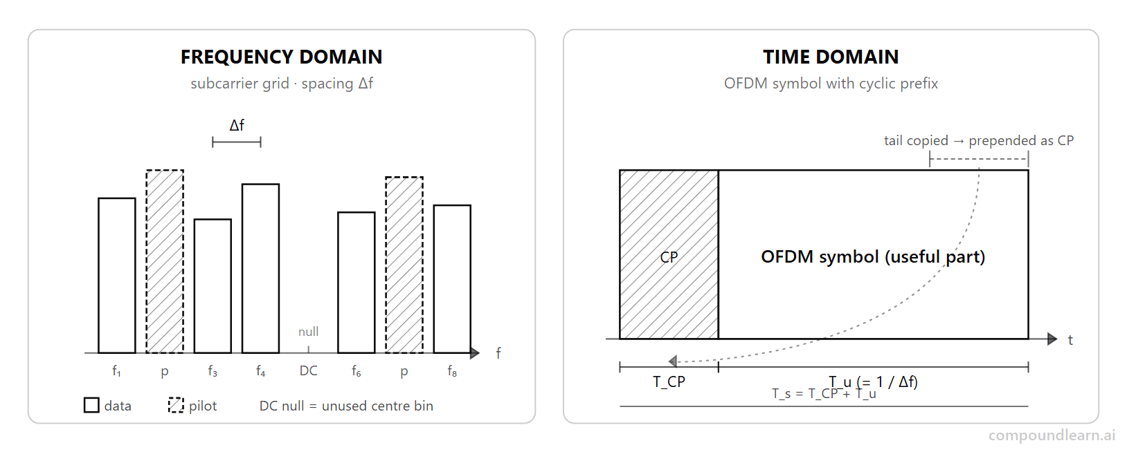
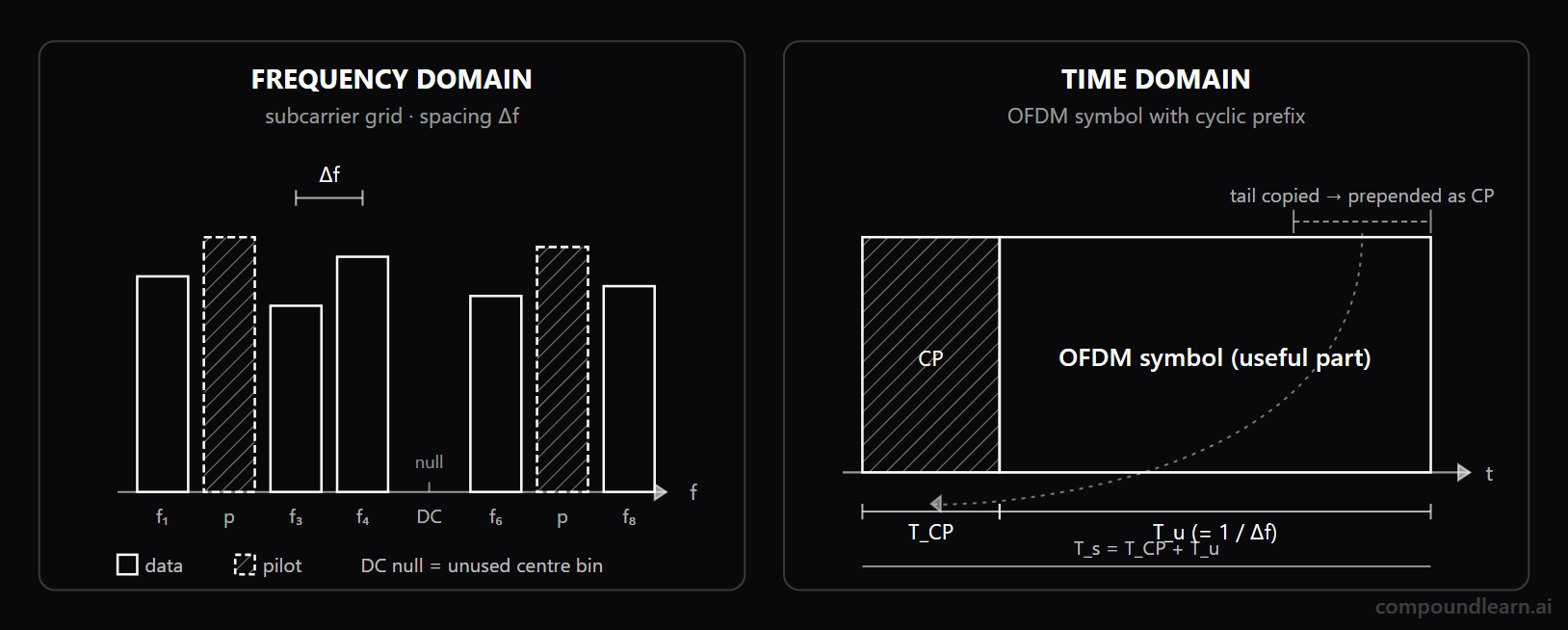
OFDM (Orthogonal Frequency-Division Multiplexing) is a multi-carrier modulation scheme that splits a wideband signal into hundreds or thousands of narrow, mutually orthogonal subcarriers, each carrying a low-rate QAM symbol stream. It is the waveform under LTE, 5G NR downlink (CP-OFDM), Wi-Fi 4 through 8 (802.11n/ac/ax/be/bn), DVB-T/T2, DAB, DOCSIS 3.1, and ADSL/VDSL — the dominant choice whenever a system needs to push high data rates through a frequency-selective channel with a tractable receiver. The engineering value of OFDM is that a multipath channel diagonalizes in the DFT basis once a cyclic prefix is in place, so frequency-domain equalization collapses to a single complex divide per subcarrier rather than a long time-domain filter. The implementation pipeline is therefore: bit-level coding and interleaving, mapping to QAM, IFFT at the transmitter, cyclic-prefix insertion, RF up-conversion; the receiver runs the inverse with frequency-domain single-tap equalization slotted between FFT and demapper. Orthogonality is preserved by spacing the subcarriers at exactly the inverse of the useful symbol duration (Δf = 1/T_u) so each FFT bin aligns with exactly one subcarrier. Its variants — DFT-spread OFDM (a.k.a. SC-FDMA) for low-PAPR uplinks, OFDMA for multi-user resource allocation, filtered and windowed OFDM for tighter spectral containment — extend the same core idea to specific deployment constraints (UE PA back-off, multi-user scheduling, adjacent-channel coexistence).
Why interviewers ask
OFDM is the fundamental "are you actually a physical-layer engineer?" benchmark. Almost every modern wireless protocol is built on it, so a candidate who cannot reason about subcarriers, the cyclic prefix, the FFT, and PAPR will not survive a depth-oriented interview at any wireless or RF role. Interviewers use OFDM questions to test three things at once: signal-processing literacy (do you understand the DFT and how circular convolution diagonalizes a channel?), system intuition (can you pick an SCS for a given delay spread and Doppler?), and implementation awareness (where do clipping, oscillator drift, and phase noise hurt you?). A good OFDM discussion quickly reveals whether a candidate has internalized the "why" behind well-known parameters — why LTE locked at 15 kHz SCS, why DOCSIS 3.1 went to 4096-QAM with smaller subcarriers, why DFT-spread OFDM exists. The interview also probes whether you can move between domains: explaining how a poorly-tuned cyclic prefix shows up as constellation rotation or as inter-symbol interference, or how a CFO presents itself as ICI in the constellation but as a frequency-domain rotation across pilot subcarriers. That fluency is the signal employers reward.
Common mistakes
The classic mistake is treating OFDM as "just FFT-based modulation" without internalizing why the cyclic prefix is mandatory. Candidates often say a guard interval prevents ISI, but cannot explain that orthogonality on the receiver depends on the channel-induced delay spread fitting inside the CP so the convolution is effectively circular. A second common error is collapsing PAPR into a single number without distinguishing instantaneous from average, or ignoring the impact on PA back-off, regulatory emission masks, and battery life. A third is conflating OFDM with OFDMA — they sound similar but are different abstraction layers (waveform vs multiple-access scheme), and many uplink-focused interviews drill down into DFT-spread OFDM for exactly this reason. Fourth, candidates over-rely on rules of thumb for FFT size and pilot density without grounding them in the channel coherence bandwidth and coherence time; the correct answer always references the channel's delay spread (sets minimum CP and maximum SCS) and Doppler (sets minimum SCS to bound ICI). Finally, many candidates forget that OFDM is sensitive to oscillator and synchronization errors: a CFO that is a tiny fraction of the SCS can destroy SINR through ICI, and phase noise becomes a hard ceiling at mmWave. Naming and quantifying these effects, even roughly, separates strong candidates from those who only memorized the textbook block diagram.
Sample interview questions
- In OFDM, why does a cyclic prefix shorter than the channel's maximum excess delay break per-subcarrier equalization at the FFT output?
- A. A shorter CP forces the receiver into time-domain Rake combining instead of FFT-based demodulation, because reduced CP lengths disable the frequency-domain equalizer block in commercial OFDM modems.
- B. A CP shorter than the maximum excess delay of the significant multipath energy lets the trailing edge of the previous symbol leak into the current FFT window, so the channel response is no longer circular and one complex divide per subcarrier cannot equalize it. ✓
- C. A shorter CP raises the sampling rate beyond the ADC bandwidth, so the receiver under-samples each subcarrier and produces aliased per-bin estimates at the FFT output stage.
- D. A shorter CP shifts the pilot subcarriers off their nominal frequency, so channel estimation diverges and the equalizer cannot lock to the data subcarriers on the rest of the FFT grid.
Option B is correct because the cyclic prefix is what converts the linear convolution by the channel into a circular convolution over the FFT window. When the CP length T_CP is at least the channel's maximum excess delay (the delay of the last significant multipath tap), the FFT window sees a clean circular convolution and the DFT diagonalizes the channel into N independent per-subcarrier taps — equalization is one complex divide per bin. Once T_CP falls below that excess delay, the trailing energy of the previous symbol bleeds into the current FFT window, the channel response inside the window is no longer circular, the per-bin model breaks, and the resulting irreducible ISI cannot be recovered by a single-tap equalizer. Option A is incorrect because OFDM receivers do not switch to Rake combining when the CP shrinks. Rake combining is a CDMA receiver structure; OFDM stays with FFT-based demodulation regardless of CP length and instead pays an ISI penalty when the CP is too short. Option C is incorrect because cyclic prefix length is independent of the sampling rate. The CP is a prepended copy of the symbol tail at the same sample rate as the rest of the waveform; shrinking it does not change the ADC bandwidth requirement. Option D is incorrect because pilot subcarriers stay on their nominal grid regardless of CP length. The CP affects the FFT window content but not the frequency assignment of pilots; the broken equalization comes from inter-symbol leakage, not pilot detuning.
- Why does OFDM exhibit high PAPR, and how does DFT-spread OFDM lower it for the LTE PUSCH and NR transform-precoded uplink?
- A. OFDM has high PAPR because each subcarrier carries a different power level; DFT-s-OFDM equalizes those powers in the time domain and the resulting flat envelope removes the back-off problem at the PA stage.
- B. OFDM has high PAPR because the cyclic prefix doubles the symbol energy; DFT-s-OFDM removes the cyclic prefix and uses a zero-guard interval instead, lowering the peak amplitude at the transmitter.
- C. The OFDM time-domain signal sums many independent subcarriers into near-complex-Gaussian time-domain samples, producing a high-dynamic-range envelope with occasional large peaks; DFT-s-OFDM precodes the symbols with an M-point DFT over the scheduled PUSCH symbol block before subcarrier mapping and the IFFT, producing a single-carrier-like waveform with 2-4 dB lower PAPR. ✓
- D. OFDM has high PAPR mainly at low SNR where receiver noise drives the envelope; DFT-s-OFDM applies a stronger LDPC code that raises the SNR floor and brings the PAPR down with it.
Option C is correct because the OFDM time-domain waveform sums many independent subcarrier components, so by the central-limit argument its time-domain samples are approximately complex Gaussian (a Rayleigh-distributed envelope magnitude) and the instantaneous peak occasionally exceeds the mean power by 8-12 dB. That forces the PA into back-off (or clipping), which kills efficiency and causes spectral regrowth into adjacent bands. DFT-spread OFDM (a.k.a. SC-FDMA, used on the LTE PUSCH and the NR uplink Transform Precoding mode) precodes the modulation symbols with an M-point DFT over the scheduled symbol block before subcarrier mapping and the IFFT — the cascade DFT-then-IFFT is mathematically equivalent to a single-carrier waveform with a frequency-domain window, so the time-domain envelope is much flatter and PAPR drops by roughly 2-4 dB. Option A is incorrect because PAPR does not come from unequal subcarrier powers; on a typical OFDM symbol each subcarrier carries the same average power. The peak arises from coherent phase alignment across many subcarriers in the time domain, not from a power-level mismatch. Option B is incorrect because the cyclic prefix is a copy of the symbol tail at the same instantaneous power as the rest of the waveform; it does not double the symbol energy, and removing it would break orthogonality rather than lower PAPR. Option D is incorrect because PAPR is a deterministic property of the modulation waveform structure; it is not driven by additive noise, and changing the channel code does not change the peak-to-average ratio of the transmitted signal.
- What UE PA back-off constraint pushes LTE/NR uplink Transform Precoding (DFT-s-OFDM) over CP-OFDM?
- A. CP-OFDM has a flatter UE envelope after the IFFT, so transform precoding is mainly selected to simplify equalization at the gNB rather than to improve PA efficiency.
- B. 3GPP often pairs DFT-s-OFDM with stricter emission-mask cases, so the waveform choice is mostly an RF-filtering shortcut; the scheduler cost is a fixed SNR loss per subcarrier.
- C. DFT-s-OFDM mainly addresses FR2 phase-noise robustness, while FR1 uplink scheduling can treat CP-OFDM and DFT-s-OFDM as equivalent PAPR cases.
- D. UE PA cost and battery budget cannot tolerate the 8-12 dB peaks of CP-OFDM, so DFT-s-OFDM lowers PAPR; the cost is reduced frequency-selective scheduling because subcarriers no longer carry independent symbols. ✓
Option D is correct because handheld UEs have tight battery and thermal budgets, and the PA dominates UL power dissipation. The CP-OFDM peak-to-average ratio (typically 8-12 dB) forces the PA to back off heavily to stay linear, wasting DC power and lowering uplink coverage at the cell edge. DFT-s-OFDM (Transform Precoding) reduces UL PAPR by 2-4 dB and is the LTE PUSCH default and an NR uplink option. The cost is that the DFT precoding step ties the symbols across the allocated subcarriers together, limiting frequency-selective scheduling and per-subcarrier link adaptation. Option A is incorrect because CP-OFDM is the high-PAPR waveform in this comparison. DFT-s-OFDM is selected for UE PA efficiency and coverage benefit, not because the gNB equalizer becomes simpler. Option B is incorrect because the uplink waveform choice is not an emission-mask shortcut. Out-of-band compliance is handled by spectrum shaping, filtering, and power limits; Transform Precoding mainly reduces PA back-off. Option C is incorrect because the FR1 NR uplink also supports DFT-s-OFDM via Transform Precoding, and LTE uses it on the PUSCH across bands. The choice is driven by PA efficiency and coverage, not by phase noise robustness alone.
- In OFDM, why does residual carrier-frequency offset (CFO) create inter-carrier interference at the FFT output in addition to common phase rotation?
- A. The FFT performs equalization of the OFDM signal, so a residual CFO is absorbed in the same FFT pass and pilot-aided phase tracking removes any leftover error with a single complex multiply per symbol.
- B. A residual CFO shifts the FFT sampling grid so each bin captures a sinc tail from its neighbors; subcarrier orthogonality holds when each bin sits exactly on a subcarrier, and the leakage scales with the square of the normalized offset. ✓
- C. The cyclic prefix gives timing slack, so a receiver can treat small CFO as another timing offset and leave pilot-aided frequency correction to later tracking loops.
- D. The LDPC decoder sees soft bits after demapping, so a receiver can rely on code redundancy to absorb the CFO energy that leaks between neighboring subcarriers.
Option B is correct because subcarrier orthogonality in OFDM relies on every FFT bin centre coinciding exactly with one subcarrier frequency. When the local oscillator carries a residual frequency offset, the FFT sampling grid slides by that offset, so each bin now sees a partial sinc tail from every neighboring subcarrier. The dominant leakage from the immediate neighbors scales roughly with the square of the normalized offset, producing the inter-carrier interference (ICI) term that limits OFDM SNR at high modulation orders. That is also why mmWave systems pick wider subcarrier spacings: the normalized phase noise stays smaller and ICI is bounded. Option A is incorrect because a residual CFO produces both a common phase rotation (CPE) — a per-symbol constellation rotation that pilot-aided tracking can largely remove — and inter-carrier interference from detuning the FFT grid; pilot-aided phase tracking alone cannot absorb the ICI term in a single complex multiply per symbol. Option C is incorrect because the CP-induced FFT-window slack tolerates small timing offsets, not carrier-frequency offsets. CFO detunes the frequency grid itself, so it must be estimated and corrected before or during FFT-domain tracking. Option D is incorrect because the LDPC decoder operates on soft bit estimates after demapping; it cannot undo ICI at the equalizer output. Residual CFO must be tracked and corrected by pilot-aided estimation before the demapper stage.
- Why does an N-point OFDM modulator use the IFFT instead of directly summing N modulated subcarrier sinusoids, and what sets the FFT size?
- A. The IFFT compresses the OFDM signal for over-the-air transmission; the FFT size is fixed at 1024 by 3GPP across every numerology and bandwidth configuration, so commercial chipsets share one optimized radix-2 datapath.
- B. The IFFT and the per-subcarrier complex multiply have identical complexity; the IFFT is chosen for its hardware reuse with the receiver-side FFT, not for arithmetic savings at the modulator stage on the transmitter side.
- C. The IFFT collapses an O(N²) per-subcarrier complex-multiply sum into an O(N log N) butterfly network; the FFT size is chosen to cover the occupied subcarriers plus guard band at the selected subcarrier spacing, often using efficient radix/mixed-radix sizes. ✓
- D. The IFFT is needed because a per-subcarrier complex multiply cannot synthesize negative-frequency subcarriers; the FFT size is determined by the number of pilot subcarriers, not the channel bandwidth allocation.
Option C is correct because synthesizing an OFDM symbol by directly summing N modulated complex sinusoids costs O(N²) multiply-add operations per output sample (N subcarriers × N samples). The IFFT exploits the symmetries of the DFT to compute the same sum with an O(N log N) butterfly network — at N = 2048 that is roughly a 100x reduction in arithmetic. The size N is chosen to cover the occupied subcarriers plus guard band at the selected subcarrier spacing, often using efficient radix/mixed-radix sizes. For example, 20 MHz at 15 kHz SCS uses N = 2048 in LTE; 100 MHz at 30 kHz SCS uses N = 4096 in NR. Option A is incorrect because the IFFT does not compress the signal; it converts frequency-domain subcarrier values to time-domain samples. The size is set by the bandwidth and SCS combination, not fixed at 1024 by 3GPP — NR FFT sizes range from 256 to 4096+ depending on numerology and channel bandwidth. Option B is incorrect because the IFFT is materially faster than direct synthesis. The O(N log N) versus O(N²) gap is the whole reason OFDM is implementable at multi-Gbps throughputs in modern chipsets. Option D is incorrect because both the IFFT and a per-subcarrier multiply can address negative-frequency subcarriers — frequency-domain indexing maps the upper half of the FFT to negative frequencies via DC-centered numbering. FFT size is bounded by bandwidth and SCS, not by the pilot count (pilots are a small fraction of the subcarriers).
- In OFDM, why do comb pilots track Doppler but need frequency interpolation, while block pilots invert that trade?
- A. A denser pilot grid improves throughput whenever lower estimator MSE outweighs pilot overhead, so comb and block choices should maximize pilot density before considering spectral efficiency.
- B. Pilot spacing can be set from delay spread and coherence bandwidth alone; once the frequency spacing is safe, Doppler has little effect on comb-versus-block placement.
- C. Pilot power mainly affects detection of the reference symbols; MMSE channel-estimation error is dominated by grid placement, so SNR_pilot is secondary to comb-versus-block geometry.
- D. Comb pilots reserve a subset of subcarriers in every OFDM symbol, so they follow time variation but interpolate across frequency; block pilots fill all subcarriers in one pilot symbol, so they capture frequency selectivity at that instant but rely on time interpolation between blocks. ✓
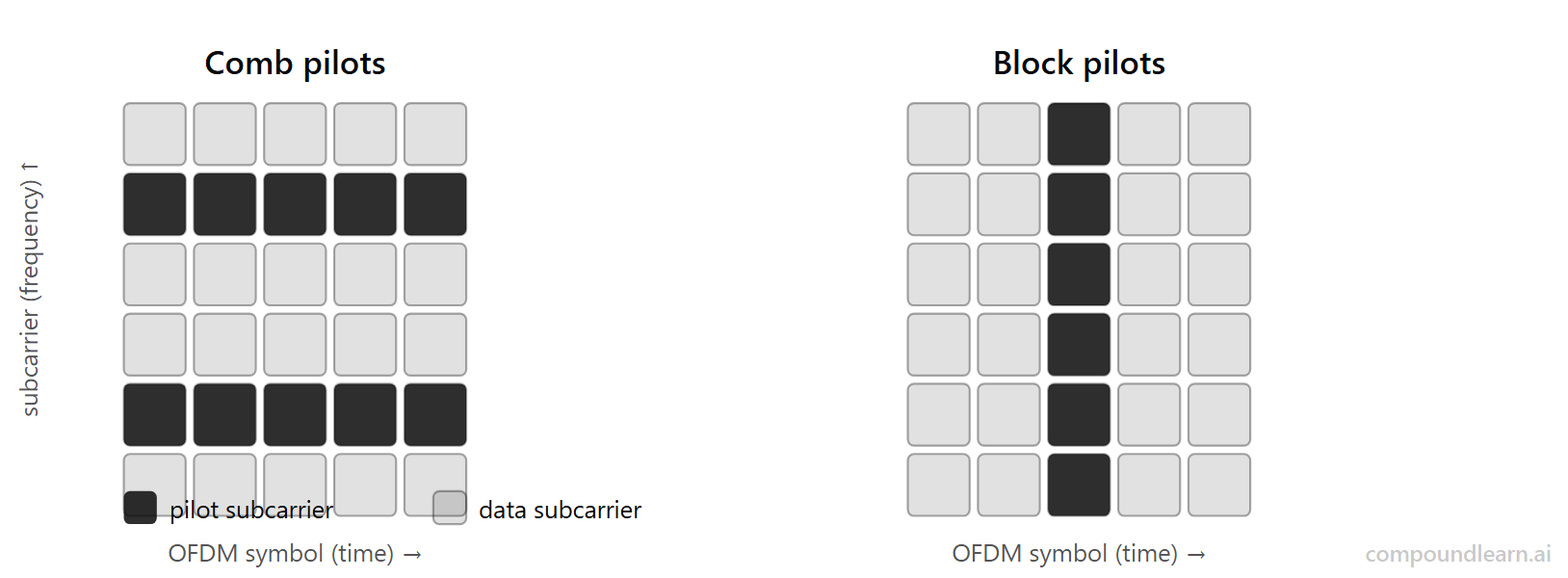
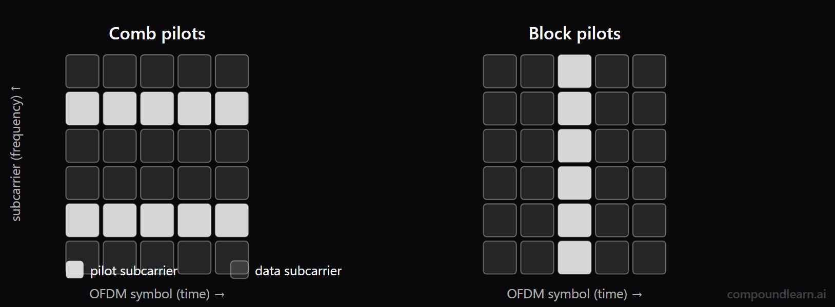
Option D is correct because pilot patterns make a deliberate time-versus-frequency tradeoff. Comb pilots place known reference values on every Kth subcarrier in each OFDM symbol, so the receiver samples the channel often in time and can track Doppler, but it must interpolate H(f) across the missing subcarriers. Block pilots dedicate one OFDM symbol to pilots across the full band, giving a clean frequency-response snapshot across subcarriers, but the receiver must interpolate in time until the next pilot block. Scattered pilots interleave both axes with a diamond or rectangular grid to balance Doppler tracking, delay-spread interpolation, and overhead. Option A is incorrect because more pilot density does not automatically improve throughput. Extra pilots reduce spectral efficiency, so a good design balances estimation MSE against pilot overhead. Option B is incorrect because pilot spacing depends on two channel-coherence axes: frequency spacing follows coherence bandwidth and delay spread, while time spacing follows coherence time and Doppler. Delay spread alone cannot choose comb versus block placement. Option C is incorrect because pilot power directly affects channel-estimation error; in a simple MMSE view, higher SNR_pilot lowers estimation MSE. Grid placement and pilot power are separate design knobs, not substitutes for each other.
- Why did NR's downlink waveform stay with windowed CP-OFDM (FFT-based, with cyclic prefix) over FBMC despite lower OOB leakage?
- A. CP-OFDM (with optional, implementation-specific spectral windowing) preserves a circular convolution, so per-subcarrier equalization is one complex divide; it composes cleanly with MIMO precoding and existing pilots, while FBMC complicates MIMO/pilot/equalization design due to intrinsic interference and synchronization sensitivity. ✓
- B. FBMC was picked because the FFT size N directly determines the signal bandwidth and FBMC packs more subcarriers per Hz than CP-OFDM, so 3GPP adopted FBMC for the NR downlink waveform during the Release 15 study item.
- C. Windowed CP-OFDM was specified by ITU-R for sub-7 GHz radio access technologies, so 3GPP had no design freedom to evaluate FBMC as the downlink waveform during the NR Release 15 study-item phase of standardisation.
- D. FBMC was selected for NR Release 16 and later; the NR Release 15 use of windowed CP-OFDM is a legacy artifact that 3GPP has since deprecated in favour of FBMC for both downlink and uplink waveforms.
Option A is correct because the NR study item explicitly evaluated FBMC, GFDM, UFMC, and windowed CP-OFDM, and chose windowed CP-OFDM for three coupled reasons. First, the cyclic prefix produces a circular convolution inside the FFT window, which means per-subcarrier equalization stays at one complex divide — FBMC subcarriers are not strictly orthogonal under MIMO precoding and require iterative interference cancellation, dramatically raising receiver complexity. Second, CP-OFDM works cleanly with existing pilot patterns (DMRS, CSI-RS) and MIMO precoding while FBMC needs new pilot designs and reciprocity calibration. Third, CP-OFDM tolerates small timing offsets via the CP slack while FBMC needs tighter symbol synchronization. The out-of-band leakage advantage of FBMC is real but is mitigated by spectral windowing on the CP-OFDM waveform, recovering most of the OOB gain without the receiver-side complexity penalty. Option B is incorrect because FBMC and CP-OFDM have comparable arithmetic complexity per sample; the FBMC penalty is at the receiver demodulator and MIMO equalizer, not the transmitter. FBMC does have measurably lower OOB leakage than naive CP-OFDM at typical SNR. Option C is incorrect because ITU-R does not specify waveform; 3GPP retained full design freedom for NR and ran a multi-waveform study item before settling on CP-OFDM as the downlink waveform. Option D is incorrect because NR uses windowed CP-OFDM on the downlink and CP-OFDM (or DFT-s-OFDM) on the uplink in Release 15 and every release since; FBMC has not been adopted in any NR release.
Frequently asked questions
- Why does OFDM use a cyclic prefix instead of a regular guard interval?
- A zero-padded guard interval would prevent inter-symbol interference between adjacent OFDM symbols, but it would not preserve the orthogonality of the subcarriers across a multipath channel. The cyclic prefix copies the tail of the symbol to the front, so once the channel-induced delay-spread fits inside the CP, the linear convolution by the channel looks like a circular convolution to the FFT. That circular convolution diagonalizes in the DFT basis, which means each subcarrier is multiplied by a single complex tap — equalization collapses to a per-subcarrier divide. A pure zero guard would require frequency-domain equalization with a much more expensive structure. Sample question aB3kL7Pq drills into the failure mode when the CP is shorter than the delay spread.
- What is PAPR and why is it a problem in OFDM systems?
- Peak-to-Average Power Ratio (see /topics/papr-peak-to-average-power-ratio) measures how much the instantaneous envelope of an OFDM time-domain signal can exceed its mean power. Because the time-domain waveform is a sum of many independent subcarrier components, by the central-limit argument the envelope is approximately Rayleigh-distributed and occasional peaks far exceed the average. High PAPR forces the power amplifier to back off (or get clipped), which kills efficiency and creates spectral regrowth that violates emission masks. Mitigation techniques range from clipping-and-filtering to selective mapping, partial transmit sequences, tone reservation, and waveform changes (DFT-spread OFDM in LTE/NR uplink) that lower PAPR by 2-4 dB. Sample questions cE9nW4Rs and dH2vT6Yj explore why the LTE/NR uplink uses DFT-s-OFDM specifically because of the UE PA back-off problem.
- How does channel estimation work in an OFDM receiver?
- OFDM channel estimation (see /topics/channel-estimation) typically rides on pilot subcarriers — known symbols inserted in a comb, block, or scattered grid. The receiver divides the received pilot subcarrier by the known transmitted value to produce raw least-squares estimates of the channel at those locations, then interpolates across frequency (and tracks across time) to fill in the data subcarriers. LTE uses CRS in a scattered diamond pattern; 5G NR uses front-loaded DMRS optionally augmented by additional DMRS symbols for high-Doppler channels. More sophisticated estimators (MMSE, basis-expansion models) leverage channel statistics to denoise the LS estimates at the cost of computation and a known correlation prior.
- How do you choose the FFT size and subcarrier spacing for an OFDM system?
- The choice is a system-level optimization. Subcarrier spacing must be much larger than the maximum Doppler shift to keep ICI low, but small enough that the corresponding OFDM symbol duration is long compared to the cyclic-prefix overhead and the channel coherence time. Once you fix SCS and bandwidth, the FFT size is essentially determined: FFT size equals signal bandwidth divided by SCS, rounded up to the next power of two for efficient implementation. Then you check that the resulting symbol duration accommodates expected delay spreads via a CP that is short relative to the symbol but long relative to the channel. 5G NR formalizes this as numerology selection, with five SCS options spanning sub-6 macro to mmWave use cases.
- What is the difference between OFDM and OFDMA?
- OFDM is a waveform: a transmitter splits its data across orthogonal subcarriers and emits a single time-domain signal occupying the full bandwidth. OFDMA is a multiple-access scheme built on OFDM: different users are assigned different subcarrier groups (resource blocks) within the same OFDM symbol, so multiple users transmit or receive simultaneously without interfering. OFDMA gives the scheduler frequency selectivity (assigning each user the subcarriers where their channel is best), better uplink power efficiency than CDMA-style spreading, and natural support for variable bit rates per user. LTE downlink, 5G NR up- and downlink, and Wi-Fi 6 (802.11ax) onward all use OFDMA — Wi-Fi 6 introduces Resource Unit (RU) sizes from 26-tone up to the full 2x996-tone allocation, while LTE locks the granularity at a 12-subcarrier Physical Resource Block.
- Why is OFDM vulnerable to frequency offsets and phase noise?
- Subcarrier orthogonality depends on each FFT bin landing exactly on the subcarrier frequency. A residual carrier-frequency offset (from oscillator drift or Doppler) shifts every subcarrier by the same fraction, so each FFT bin captures part of its neighbors — that is inter-carrier interference (ICI), and it scales roughly with the square of the normalized offset. Phase noise broadens each subcarrier into a skirt that leaks into adjacent bins; the closer the SCS, the larger the relative leakage, which is why mmWave systems use wider SCS (120-240 kHz) to keep phase-noise-induced ICI bounded. Receivers compensate via pilot-aided CFO estimation and common phase error correction at every symbol. Sample question fM5xC1Wb walks through the ICI mechanism explicitly.
- How does OFDM compare to FBMC (Filter Bank Multi-Carrier) and why did 5G NR pick OFDM?
- FBMC replaces the rectangular FFT window of CP-OFDM with a prototype filter that has much lower out-of-band leakage, so adjacent-channel emissions can be 30-40 dB lower than CP-OFDM at the band edges. The cost is severe: FBMC subcarriers are only orthogonal under tight synchronization, MIMO precoding breaks their orthogonality (requiring iterative receiver-side interference cancellation), there is no cyclic prefix to tolerate timing offsets, and the prototype-filter design adds latency. The NR study item evaluated FBMC, GFDM, UFMC and several other candidates and picked windowed CP-OFDM (downlink) plus CP-OFDM or DFT-s-OFDM (uplink) because the MIMO + reciprocity + low-latency story is much cleaner. Spectral windowing on CP-OFDM recovers most of the OOB leakage advantage of FBMC without breaking the MIMO precoder. Sample question kS2dA9Fr drills into this design rationale.
- Why does OFDM rely on the cyclic-prefix copy of the symbol tail rather than any other guard structure, and what does the CP actually buy mathematically?
- A zero-padded guard would prevent symbol-to-symbol leakage but would leave the FFT window seeing a truncated, non-circular convolution of the channel impulse response with the current symbol. The DFT only diagonalizes a circular convolution, so a zero guard would force the receiver into a much more expensive structured equalizer instead of one complex divide per subcarrier. The cyclic prefix is a copy of the symbol tail prepended to the front, so — as long as the channel delay spread fits inside T_CP — the FFT window observes a clean circular convolution. That circularity is what diagonalizes the channel in the DFT basis, and that diagonalization is what makes OFDM cheap enough to deploy at 100-MHz-class bandwidths. The cost is the CP overhead (typically 7% to 25% of the symbol duration depending on numerology), which is a small price for a single-tap-per-subcarrier equalizer.
- How does 5G NR extend OFDM with scalable numerology?
- NR parameterizes the OFDM subcarrier spacing as SCS = 15·2^μ kHz where μ ranges from 0 to 4 — giving 15, 30, 60, 120, and 240 kHz options. Symbol duration scales inversely with SCS, slot duration scales as 1 ms / 2^μ, and CP duration scales proportionally with the symbol. This lets the same waveform serve large sub-6 GHz cells (low μ, long CP, robust to long delay spread) and small mmWave cells (high μ, short slot, low latency) under one PHY. Different numerologies coexist on the same carrier via separate Bandwidth Parts (BWPs). See /topics/nr-bwp-and-numerology for the BWP-level architecture and switching mechanism.
Related topics
Pillar
Siblings
- Wireless Foundations
- MIMO Explained: Spatial Multiplexing, Rank, Massive MIMO
- Beamforming Interview Guide: Analog vs Digital vs Hybrid
- DSP Fundamentals
- Antenna Design
- Channel Estimation
- Link Budget
- Signals and Systems
- EVM (Error Vector Magnitude) in Wireless RF Test and Design
- PDCCH, PDSCH, PUCCH, PUSCH: The 5G NR Physical Channels
- LDPC Codes in Wireless (Wi-Fi 6+ / 5G NR / DVB-S2)
Practice
Essential AI-Native Skills for OFDM Explained: Subcarriers, Cyclic Prefix, PAPR, and OFDMA
Modern engineering work increasingly uses AI tools for design and code review, debugging, documentation, test and testbench generation, and workflow automation. The goal is not to let AI replace engineering judgment — it is to move faster while keeping verification discipline.
- Use AI to explain unfamiliar code, logs, waveforms, datasheets, or test failures.
- Break large problems into small, reviewable steps you can verify independently.
- Ask AI for hypotheses, then validate them against tests, measurements, simulations, or lab data.
- Version-control your analysis scripts, testbenches, and configs — keep changes small and reviewable.
- Document your assumptions, design tradeoffs, and debugging decisions.
- Verify AI output before trusting it: run the checks that fit the domain — unit tests, linters, simulations, or bench/lab measurements.
- Review AI output for correctness, edge cases, and real-world consequences.