Mach-Zehnder Modulators Explained: Vπ, Chirp, and Bias Interview Prep
Mach-Zehnder modulators explained: the electro-optic effect, Vπ, push-pull drive/bias point, and chirp — how optical transmitters encode symbols in coherent links.
Quick answer
The Mach-Zehnder modulator (MZM) is the workhorse high-speed optical modulator for coherent and direct-detection transmitters across long-reach, metro, datacenter, and increasingly CPO applications.
MZM topics are probed in any optical-transmitter, transceiver-design, or silicon-photonics interview (see /topics/silicon-photonics-engineer-interview-signals) because the MZM is the dominant high-speed modulator and the choice of V_π, V_π·L, and material platform shapes every transmitter design decision.
Editorial review
Written by
CompoundLearn editorial team
Wireless / RF / hardware engineering
Reviewed by
CompoundLearn editorial team
Wireless / RF / hardware engineering
Last reviewed
Built from curated topic maps, editorial validation, and subject-matter review so the page stays aligned with the interview intent and the current content pipeline.
What it is
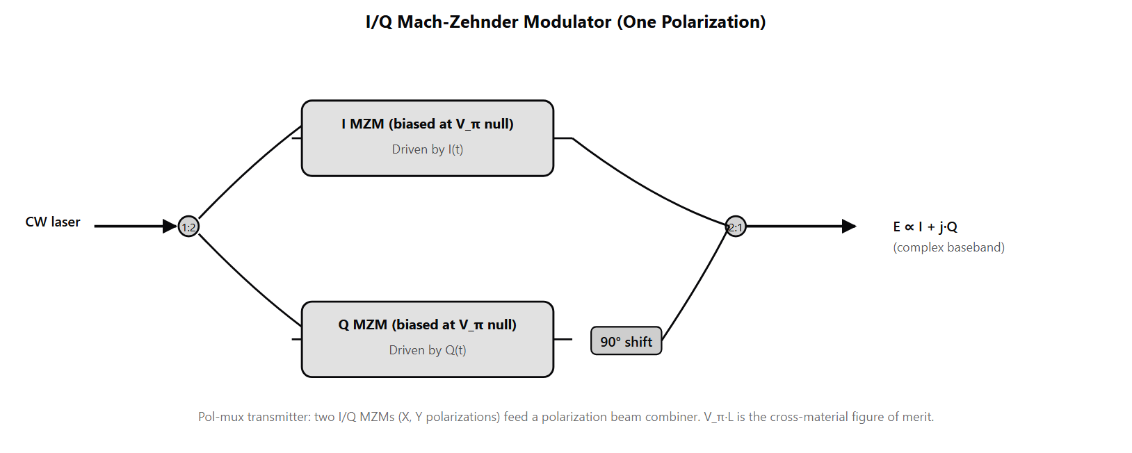
The Mach-Zehnder modulator (MZM) is the workhorse high-speed optical modulator for coherent and direct-detection transmitters across long-reach, metro, datacenter, and increasingly CPO applications. Architecturally an MZM is an electro-optic device: input light is split into two arms by a 1:2 coupler; each arm experiences a phase shift proportional to an applied voltage through the electro-optic effect in the underlying material; the two arms are recombined at a 2:1 output coupler where their phase difference determines the output intensity. The output transfer characteristic is a cosine-squared function of the phase difference, with the operating point set by the DC bias. Two operating-point choices matter. Biased at the quadrature point (half-V_π bias), the MZM produces intensity modulation linear in drive voltage — used for direct-detection IM-DD transmitters. Biased at the null point (V_π peak), the output passes through zero with sign-preserving modulation around the null — used as a child stage in I/Q MZM transmitters for coherent modulation. The I/Q MZM (also called the nested or quadrature MZM) is the coherent-transmitter architecture. Two parallel child MZMs, each biased at the null point, sit inside an outer Mach-Zehnder structure with a fixed 90° relative phase shift between the two arms. One child drives the in-phase component; the other drives quadrature; the 90° relative phase shift makes them orthogonal components of the optical field. The output is the complex baseband E ∝ I + j·Q, which is what coherent receivers demodulate. A polarization-multiplexed transmitter uses two I/Q MZMs feeding a polarization beam combiner, producing four independent baseband streams modulated onto two polarizations — the architecture behind DP-QPSK, DP-16QAM, DP-64QAM, and PCS-QAM. V_π — the half-wave voltage — is the voltage swing required to shift one MZM arm by π radians. It is the primary spec for any MZM because it directly sets driver power and signal-integrity requirements. V_π·L — the product of V_π and modulator length — is the cross-material figure of merit because it captures the intrinsic efficiency of the material+geometry pair. Bulk lithium niobate has V_π·L in the 12–25 V·cm range and modulators are several cm long. Thin-film lithium niobate (TFLN) achieves V_π·L of 1–3 V·cm, an order-of-magnitude efficiency gain that enables shorter modulators with lower drive voltage. Silicon-photonics depletion-mode modulators are in the 10–20 V·cm range; their CMOS-compatible fabrication is their main advantage. Indium phosphide modulators sit at 5–8 V·cm with integration advantages for InP-laser-integrated transmitters. Extinction ratio (ER) and chirp are the operational performance specs. ER is the dB ratio between "on" and "off" output power for intensity-modulated signals; it bounds the achievable on/off contrast and ultimately the system link budget. Typical high-quality MZMs achieve 10–13 dB ER. Chirp is unintended phase modulation that accompanies amplitude modulation when the two MZM arms are not perfectly balanced or when the drive voltage induces correlated refractive-index and absorption changes. Chirp interacts with chromatic dispersion in fiber (see /topics/optical-fiber-impairments) to produce additional pulse broadening; coherent DSP largely undoes this but the residual still costs OSNR margin. "Chirp-free" MZM designs use symmetric electrodes and accurate bias control to keep chirp below 0.1 dB.
Why interviewers ask
MZM topics are probed in any optical-transmitter, transceiver-design, or silicon-photonics interview (see /topics/silicon-photonics-engineer-interview-signals) because the MZM is the dominant high-speed modulator and the choice of V_π, V_π·L, and material platform shapes every transmitter design decision. A candidate who fluently navigates V_π vs V_π·L, bias-point selection (quadrature vs null), I/Q MZM parallel architecture, and material trade-offs (LN vs TFLN vs silicon vs InP) is showing the integrated transmitter-design understanding that staff optical-transmitter and CPO-design roles (see /topics/optical-engineer-interview-signals) require. The V_π·L figure-of-merit is the deepest interview question. Strong candidates explain that V_π alone is misleading — a long modulator with low V_π can be less efficient than a short modulator with higher V_π — and that V_π·L is the material+geometry comparison metric. They can quote material-class V_π·L numbers (bulk LN 12–25, TFLN 1–3, silicon 10–20, InP 5–8) and explain that TFLN's order-of-magnitude V_π·L advantage is what is driving new 800G+ coherent transceiver designs. The I/Q MZM architecture is the design-rationale question. Strong candidates explain that a single MZM can only produce intensity modulation (or binary phase shifts at the null), but coherent transmission requires independent I and Q control; the parallel I/Q MZM with 90° relative phase shift between the two child MZMs is the architecture that delivers complex-baseband modulation. Weak candidates name "MZM" without distinguishing single vs I/Q nested architecture. Chirp is the operational-detail question that separates strong candidates. A candidate who can explain that chirp comes from arm asymmetry or material-level correlated effects, that it interacts with chromatic dispersion in fiber to produce additional impairment, and that "chirp-free" MZM design is a specification target reveals deployment experience. Candidates who do not surface chirp at all have not worked at the transmitter-characterization level. Bias-point selection is the basic-fluency question. A candidate who can switch between quadrature-bias (intensity modulation for direct detection) and null-bias (sign-preserving for I/Q child stages) reveals competent transmitter understanding; a candidate who treats "MZM bias" as a single concept misses the architectural distinction between direct-detection and coherent transmitters.
Common mistakes
The most common mistake is comparing modulators by V_π alone. A 5 cm bulk LN modulator at V_π = 4 V has V_π·L = 20 V·cm; a 1 cm TFLN modulator at V_π = 2 V has V_π·L = 2 V·cm. The TFLN is 2× more efficient per volt AND 5× shorter — that combination is what makes TFLN the leading platform for new high-rate coherent designs. Candidates who compare on V_π alone miss the cross-material efficiency comparison. A second gap is missing the I/Q MZM parallel architecture. Some candidates describe a "phase modulator" as one MZM with biasing, missing the fact that independent I and Q control requires two parallel child MZMs with 90° relative phase shift. Coherent modulation formats (QPSK, QAM) cannot be produced from a single MZM no matter how it is biased. Candidates who do not name the parallel-nested architecture have not worked at the coherent-transmitter level. A third gap is treating chirp as theoretical. Production MZMs do generate measurable chirp, and the chirp interacts with chromatic dispersion in fiber to produce additional impairment. Coherent DSP largely undoes this in receivers, but the residual penalty is real and "chirp-free" design is a specification target. Candidates who dismiss chirp as a non-issue have not faced production transmitter characterization data. A fourth gap is conflating bias point with modulator type. Quadrature-bias and null-bias are two operating points of the same MZM, used for different purposes: quadrature for intensity modulation (direct-detection), null for sign-preserving modulation (coherent I/Q child stages). Candidates who treat "MZM bias" as one concept miss the architectural distinction. A fifth gap is missing the MZM-vs-ring-modulator comparison. MZMs are broadband (any wavelength inside the operating range works) and large (mm-cm length); ring modulators are narrowband (resonance-limited) and compact (tens of microns). Datacenter short-reach and CPO applications increasingly use ring modulators because of their size and power advantages; long-reach coherent uses MZMs because of their broadband operation and high extinction. Candidates who treat MZM as the only modulator architecture miss the datacenter-optics shift to rings. See /topics/coherent-modulation-formats for the coherent-modulation context, /topics/coherent-optical-detection for the receiver-side architecture, and /topics/silicon-photonics-datacenter (queued) for the datacenter-optics ring-vs-MZM trade-off.
MZM Material Platforms — V_π·L and Best Use
| Platform | V_π·L (V·cm) | Typical V_π | Length | Bandwidth | Best Application |
|---|---|---|---|---|---|
| Bulk LiNbO3 | 12–25 | 3–6 V | 3–10 cm | >40 GHz | Established long-reach coherent |
| Thin-film LN (TFLN) | 1–3 | 1–3 V | 0.5–2 cm | >100 GHz | New 800G+ coherent transceivers |
| Silicon (depletion-mode) | 10–20 | 4–8 V | 0.5–1 cm | 50–60 GHz | CMOS-integrated transceivers, datacenter |
| Indium phosphide | 5–8 | 2–5 V | ~1 cm | >40 GHz | InP-laser-integrated transceivers |
Sample interview questions
- An I/Q MZM transmitter is implemented as two parallel MZMs nested inside an outer interferometer with a fixed 90° phase shift between the two arms. Why is this parallel structure required for coherent modulation, and why not just one MZM with more careful biasing?
- A. A single MZM with careful biasing produces I and Q simultaneously; the parallel structure is redundancy.
- B. A single MZM can only modulate the real part of the optical field (intensity modulation through phase-difference interference). To independently modulate both I and Q components — required for QPSK, QAM, and any phase-modulation format — the transmitter needs two parallel MZMs each driving one quadrature, then combined with a 90° relative phase shift. Each child MZM is biased at the null point (V_π peak) so it produces zero output at zero drive, with sign-preserving modulation around that null. ✓
- C. The parallel structure is needed only for polarization multiplexing, not for I/Q modulation.
- D. The parallel structure is required only at FR2 frequencies.
Option B is correct. A single MZM creates intensity modulation by interferometric combination of two arm-paths with a relative phase difference; its transfer characteristic is the well-known cosine-squared (or shifted by bias). It can produce phase shifts of 0 or π in the optical field — effectively a binary phase shift keyed signal at best — but it cannot independently set the in-phase and quadrature components. The I/Q MZM (also called nested MZM or quadrature MZM) consists of two parallel child MZMs inside an outer Mach-Zehnder structure with a fixed 90° relative phase shift between the two arms. Each child MZM is biased at the null point (V = V_π peak) where the output passes through zero with sign-preserving modulation around the null — when V swings positive the output is positive; when V swings negative the output is negative (a π-phase-shifted signal). The two child MZMs drive the I and Q components independently, the 90° relative phase shift converts them into orthogonal components of the optical field, and the output is E ∝ I + j·Q. This is the architecture that enables QPSK, QAM, and PCS-QAM transmission. A polarization-multiplexed transmitter uses two I/Q MZMs (one per orthogonal polarization) feeding a polarization beam combiner, producing 4 independent baseband streams modulated onto two polarizations of one carrier — the input to DP-QPSK, DP-16QAM, DP-64QAM transmission. Option A misses that a single MZM is intensity-only. Option C is wrong — pol-mux requires two complete I/Q stages, not just I/Q. Option D is wrong — the parallel I/Q structure is required at all frequencies for coherent modulation. Production reality: integrated I/Q MZM transmitters are the dominant coherent transmitter architecture. The integration is increasingly silicon-photonics-based for short-reach and lithium-niobate-on-silicon for long-reach where V_π·L tradeoffs favor LN.
- A Mach-Zehnder modulator has V_π = 4 V and V_π·L figure of merit of 20 V·cm. What does V_π·L tell you about the modulator design, and why is it a more useful comparison metric than V_π alone?
- A. V_π·L tells you nothing useful; only V_π matters for driver design.
- B. V_π·L is the product of the half-wave voltage and the modulator length, and it captures the fundamental efficiency of the electro-optic interaction in the material. A small V_π·L means more efficient modulation per unit length — useful when designing for compact footprint or low drive voltage. Comparing V_π alone is misleading because a long modulator can have low V_π but at the cost of footprint, and a short modulator can have high V_π but at the cost of driver power. V_π·L is the material+geometry figure-of-merit that lets you compare modulators built from different materials (LiNbO3, thin-film LN, silicon, InP) on a fair basis. ✓
- C. V_π·L only applies to ring modulators, not Mach-Zehnders.
- D. V_π·L is only relevant in submarine deployments.
Option B is correct. The product V_π·L (half-wave voltage × modulator length) is the standard figure-of-merit for electro-optic modulators because it captures the intrinsic efficiency of the material+geometry pair. Lower V_π·L means more efficient modulation per unit length, which gives the designer headroom to choose between (a) shorter modulator for compact footprint or (b) lower drive voltage for low-power drivers. Material comparisons at the V_π·L level: - Bulk LiNbO3 (lithium niobate): V_π·L typically 12–25 V·cm; mature, low-loss, very high-frequency capable. The standard for high-performance long-reach coherent transmitters for two decades. - Thin-film LN (TFLN) on insulator: V_π·L 1–3 V·cm, an order of magnitude improvement; the emerging high-performance technology that combines LN's excellent EO coefficient with stronger optical confinement. - Silicon (depletion-mode): V_π·L 10–20 V·cm; CMOS-compatible fabrication is the big advantage, but V_π is higher than the LN family for equal length. - Indium phosphide (InP): V_π·L 5–8 V·cm; competitive efficiency, allows integration with InP lasers. Why V_π alone is misleading: a 5 cm bulk LN modulator with V_π·L = 20 V·cm has V_π = 4 V. A 1 cm thin-film LN modulator with V_π·L = 2 V·cm has V_π = 2 V. The TFLN is 2× more efficient on the driver side AND 5× shorter — that combination is what makes TFLN the leading technology for new high-rate coherent designs. Option A misses that V_π·L is the cross-material comparison metric. Option C is wrong — V_π·L applies to MZMs, not ring modulators (rings use a different efficiency metric tied to resonance shift per applied voltage). Option D is unrelated to deployment scenario. Production reality: transceiver-chip vendors quote V_π·L as a primary spec because it drives both driver-power and chip-area trade-offs in the package.
- A Mach-Zehnder modulator exhibits 0.3 dB of residual modulation chirp at high baud rates. What causes the chirp, and why does it matter for long-reach links?
- A. Chirp is irrelevant in optical systems and has no practical effect.
- B. Chirp is unintended phase modulation that accompanies amplitude modulation when the two MZM arms are not perfectly balanced or when the drive voltage causes refractive-index changes correlated with intensity changes. A small amount of chirp interacts with chromatic dispersion in fiber to produce additional pulse broadening or distortion that the receiver-side DSP must compensate. For coherent systems with full-DSP CD compensation the impact is small but not zero; for direct-detection systems chirp can cause real BER degradation. MZM design specifies low chirp (often "chirp-free" balanced configurations) to minimize this. ✓
- C. Chirp is only generated by ring modulators, not MZMs.
- D. Chirp only matters in submarine systems.
Option B is correct. Chirp in an MZM is unintended frequency (phase) modulation that accompanies the desired amplitude modulation. Sources: - Asymmetric drive: if the two MZM arms are driven with non-symmetric voltages or have non-identical electrodes, the per-arm phase shifts are not exactly anti-symmetric and the combined output picks up a small phase shift correlated with the intensity change. - Material-level effects: in silicon-depletion-mode modulators, the carrier-depletion changes both the refractive index and the absorption (free-carrier absorption + plasma dispersion); these effects can be correlated with the desired modulation, producing chirp. - Imperfect bias control: if the MZM is not held precisely at the operating null point, the operating point drifts and the modulation curve becomes asymmetric, producing chirp. Chirp matters because: - Chromatic dispersion in fiber interacts with chirp: a chirped pulse propagating through CD experiences additional broadening or compression depending on the sign of the chirp and the dispersion. For direct-detection systems with limited CD compensation, this is a real BER cost. - For coherent systems with full-DSP CD compensation, the receiver can largely undo the chirp+dispersion interaction, so the residual penalty is small. But excessive chirp still costs OSNR margin because the receiver's phase-recovery and equalization blocks consume some of their budget on it. A "chirp-free" or "balanced" MZM is designed with symmetric arm electrodes and accurate bias control to drive chirp to <0.1 dB. Silicon-photonics MZMs sometimes specify chirp parameter alpha (the linewidth-enhancement-factor analog for modulators) as a quality metric. Option A misses the dispersion-interaction story. Option C is wrong — chirp is an MZM phenomenon (ring modulators have their own chirp characteristics too, but MZM chirp is the more-discussed case). Option D is unrelated to deployment scenario. Production reality: chirp specification appears on every coherent transmitter datasheet, with chirp-free designs preferred for any long-reach application.
Frequently asked questions
- What is a Mach-Zehnder modulator?
- A Mach-Zehnder modulator (MZM) is an electro-optic device that modulates an optical carrier by interferometrically combining two phase-shifted optical arm paths. Input light is split into two arms; each arm experiences an electro-optic phase shift proportional to an applied voltage; the arms are recombined at an output coupler. The output intensity is a cosine-squared function of the phase difference between the arms. The MZM is the workhorse optical-modulator architecture for high-speed coherent and direct-detection transmitters because (a) it operates at the modulation speeds needed (tens to hundreds of GHz), (b) it can be biased at the linear point of the transfer curve for direct-detection or at the null point for sign-preserving I/Q modulation, and (c) it integrates well into silicon-photonics, lithium-niobate, indium-phosphide, and thin-film-LN material platforms.
- What is V_π?
- V_π is the voltage swing required to shift the phase of one MZM arm by π radians. It is a primary specification for any electro-optic modulator because it determines how much voltage the driver needs to swing for full modulation — directly setting the driver power, the linearity requirements, and the optical extinction ratio. Lower V_π means less driver power and more headroom; typical V_π values in 2026: 1–3 V for thin-film-LN MZMs at 100 GBaud, 3–6 V for bulk LiNbO3 MZMs, 4–8 V for silicon-photonics depletion-mode MZMs. The driver electrical signal must swing from approximately −V_π to +V_π around the null bias point to produce a full modulation swing.
- What is V_π·L and why is it used?
- V_π·L is the product of V_π and the modulator length, expressed in units of V·cm. It captures the intrinsic electro-optic efficiency of the material+geometry pair: a small V_π·L means efficient modulation per unit length, which lets the designer choose between (a) a short modulator with moderate V_π or (b) a long modulator with low V_π — depending on the package constraints. V_π·L is the cross-material figure-of-merit because it lets you compare MZMs built from different materials on a fair basis. Bulk LiNbO3 V_π·L is typically 12–25 V·cm; thin-film LN drops this to 1–3 V·cm; silicon-depletion 10–20 V·cm; InP 5–8 V·cm. The thin-film LN advantage is the primary reason TFLN is winning new coherent designs.
- What is extinction ratio?
- Extinction ratio (ER) is the ratio between the "on" and "off" output power of an intensity-modulated signal, expressed in dB. For an MZM biased at the quadrature point (V_bias = V_π / 2) and modulated with a swing of V_π, ideal ER is infinite (perfect on/off contrast). In practice, ER is finite because of (a) imperfect bias control, (b) arm-loss imbalance, (c) limited drive-voltage swing relative to V_π. Typical MZM ER is 10–13 dB for high-quality modulators; ER below 10 dB starts to cost link OSNR because the off-state leaks signal. For coherent I/Q modulators, ER per arm is less critical because the receiver demodulates the complex field rather than measuring on/off intensity, but per-arm ER still bounds the achievable constellation cleanliness.
- What is chirp in an MZM?
- Chirp is unintended phase modulation that accompanies the desired amplitude modulation. It arises from (a) imperfect symmetry between the two MZM arms (so the desired anti-symmetric phase shifts produce a small net common-mode phase shift), (b) material-level effects that correlate refractive index with the modulation drive (especially in silicon-depletion-mode modulators where carrier injection changes both phase and absorption), and (c) imperfect bias control that drifts the operating point. Chirp matters because it interacts with chromatic dispersion in the fiber: a chirped pulse propagating through CD experiences additional broadening or compression. For direct-detection systems this is a real BER cost; for coherent systems with full-DSP CD compensation the impact is largely recoverable but still consumes some OSNR margin. "Chirp-free" MZM designs use symmetric electrode layouts and accurate bias-control to keep residual chirp below 0.1 dB.
- How does the I/Q MZM architecture work?
- An I/Q MZM (also called a nested MZM or quadrature MZM) consists of two parallel child MZMs inside an outer Mach-Zehnder structure, with a fixed 90° relative phase shift between the two arms. Each child MZM is biased at the null point (V_π peak) where the output passes through zero with sign-preserving modulation around the null. The two child MZMs drive the in-phase (I) and quadrature (Q) components independently, the 90° relative phase shift converts them into orthogonal components of the optical field, and the output is E ∝ I + j·Q. A polarization-multiplexed transmitter uses two I/Q MZMs (one per polarization) feeding a polarization beam combiner, producing 4 independent baseband streams modulated onto two polarizations of one carrier — the basic transmit architecture for DP-QPSK, DP-16QAM, and DP-64QAM coherent transmission.
- What is lithium niobate (LN) vs thin-film LN vs silicon-photonics MZM?
- Bulk lithium niobate (LiNbO3) was the dominant high-performance MZM material for two decades — strong electro-optic coefficient, very low loss, very high bandwidth. V_π·L is 12–25 V·cm; the modulators are several cm long. Thin-film lithium niobate (TFLN, also called LN-on-insulator) thins the LN to sub-micron thickness on a SiO2 buffer layer, dramatically increasing optical-mode confinement and electric-field overlap; V_π·L drops to 1–3 V·cm, and modulators shrink to under 1 cm. Silicon photonics uses silicon's plasma-dispersion effect for modulation in depletion-mode MZMs; V_π·L is 10–20 V·cm, V_π is higher, but the CMOS-compatible fabrication enables high-volume integration with other photonic functions. TFLN is winning new long-reach coherent designs because of its V_π·L advantage; silicon is winning short-reach datacenter and integrated-coherent designs because of its integration advantages.
- How does an MZM compare to a ring modulator?
- A Mach-Zehnder modulator works via interferometric combination of two phase-shifted arms; modulation works across a broad optical band, but the device is long (millimeters to centimeters). A ring modulator works via resonance shift: applied voltage tunes the resonance frequency of a small microring, shifting which wavelengths pass through. Ring modulators are very compact (tens of microns), very low-power per bit, but bandwidth-limited (resonance Q gives narrow operating range) and thermally sensitive (resonance shifts with temperature, requiring active thermal stabilization). For datacenter short-reach and CPO applications where power and area matter, ring modulators win. For long-reach coherent where broad-band operation and high extinction matter, MZMs win. See /topics/silicon-photonics-datacenter (queued) for the ring-modulator-vs-MZM trade-off in datacenter optics context.
Related topics
Siblings
- Coherent Modulation Formats: DP-QPSK, 16QAM, PCS Explained
- Coherent Optical Detection: How DSPs Replaced Direct Detection
- Silicon Photonics for Datacenters Explained: 800G+ Links
- CPO vs Pluggable Optics: Density, Power & AI-Cluster Trade-offs
- Silicon Photonics Engineer Interview Signals
- Optical Engineer Interview Signals: What Interviewers Probe
Essential AI-Native Skills for Mach-Zehnder Modulators Explained: Vπ, Chirp, and Bias
Modern engineering work increasingly uses AI tools for design and code review, debugging, documentation, test and testbench generation, and workflow automation. The goal is not to let AI replace engineering judgment — it is to move faster while keeping verification discipline.
- Use AI to explain unfamiliar code, logs, waveforms, datasheets, or test failures.
- Break large problems into small, reviewable steps you can verify independently.
- Ask AI for hypotheses, then validate them against tests, measurements, simulations, or lab data.
- Version-control your analysis scripts, testbenches, and configs — keep changes small and reviewable.
- Document your assumptions, design tradeoffs, and debugging decisions.
- Verify AI output before trusting it: run the checks that fit the domain — unit tests, linters, simulations, or bench/lab measurements.
- Review AI output for correctness, edge cases, and real-world consequences.
Mach-Zehnder Modulators Explained: Vπ, Chirp, and Bias — coming to the question bank
The adaptive practice engine is already live for core wireless, RF, and ML systems. Mach-Zehnder Modulators Explained: Vπ, Chirp, and Bias isn't covered in the question bank yet — get notified when it's added.