Optical Fiber Impairments Explained: CD, PMD, Nonlinearity Interview Prep
Optical fiber impairments explained: chromatic dispersion, PMD, attenuation, and Kerr nonlinearities (SPM, XPM, FWM) — how each limits reach; coherent DSP fixes CD/PMD while FEC and power design handle the rest.
Quick answer
Optical fiber is not the noise-free linear medium that introductory optics treats it as.
Fiber impairments are the deep-physics interview topic in optical-engineering roles (see /topics/optical-engineer-interview-signals) because the candidate has to integrate fiber physics, DSP compensation, and operational fiber-plant choices into one coherent mental model.
Editorial review
Written by
CompoundLearn editorial team
Wireless / RF / hardware engineering
Reviewed by
CompoundLearn editorial team
Wireless / RF / hardware engineering
Last reviewed
Built from curated topic maps, editorial validation, and subject-matter review so the page stays aligned with the interview intent and the current content pipeline.
What it is
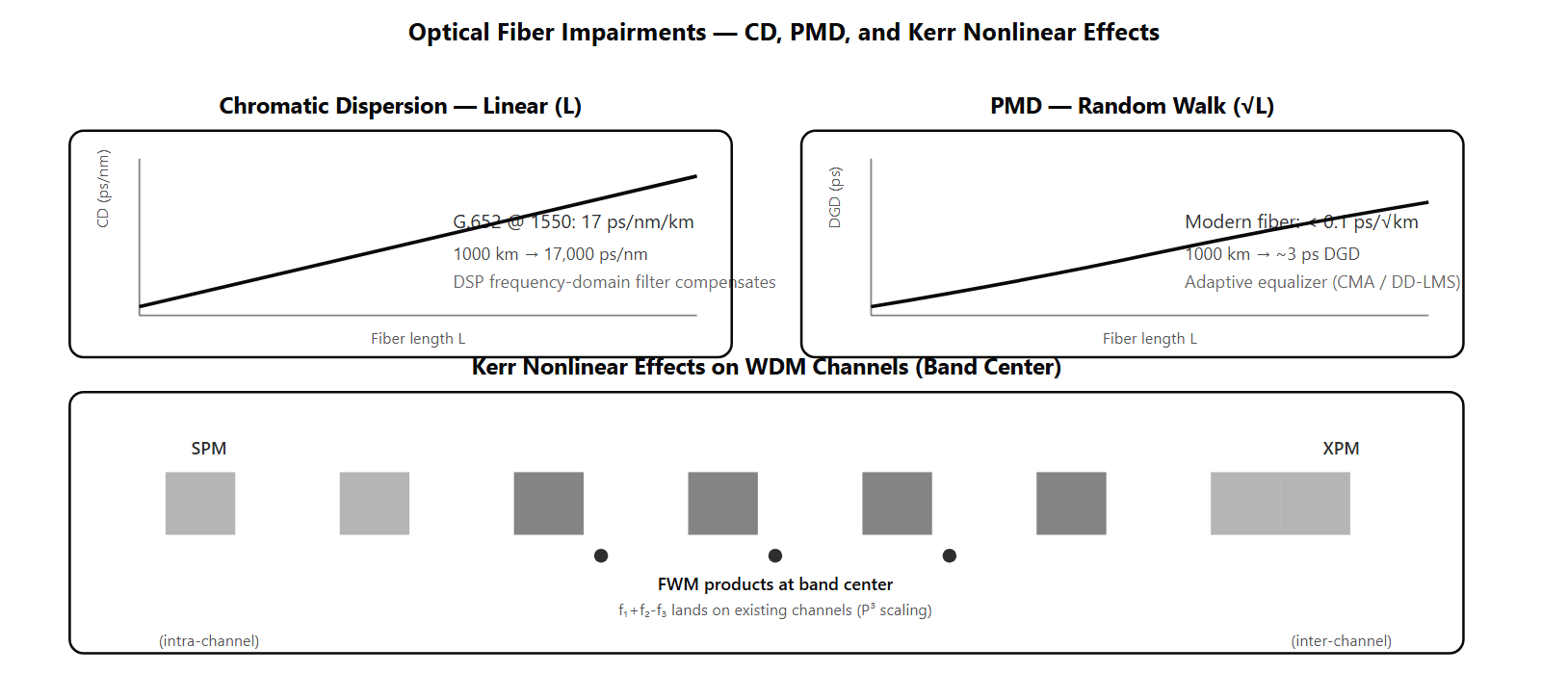
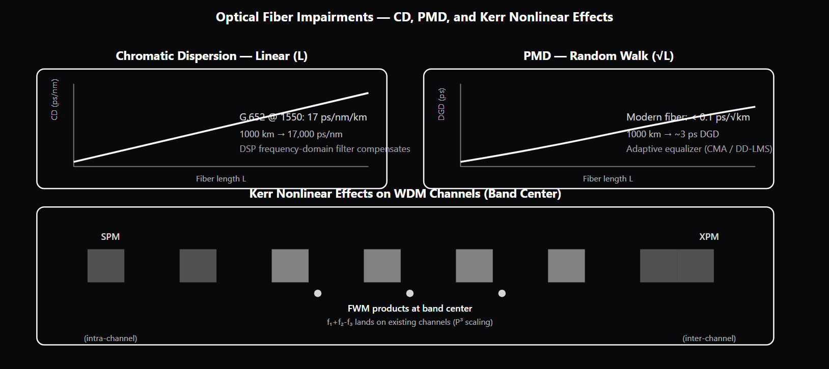
Optical fiber is not the noise-free linear medium that introductory optics treats it as. Real long-distance fiber transmission encounters a series of impairments that distort, spread, and corrupt the optical signal — and managing these impairments is the central engineering challenge of long-haul optical transport. The impairments split into three categories with different statistical properties and compensation strategies. **Linear deterministic impairments — chromatic dispersion (CD).** Different spectral components of an optical pulse propagate at slightly different group velocities in silica fiber. The CD coefficient for G.652 single-mode fiber at 1550 nm is approximately 17 ps/nm/km — two components 1 nm apart accumulate 17 ps of relative delay per km. CD accumulates linearly with fiber length, so a 1000 km link has 17,000 ps/nm of total CD. For a 64 GBaud signal with ~0.5 nm spectral width this spreads each symbol across hundreds of received symbols, making the channel unusable without compensation. Coherent DSP compensates CD as a frequency-domain filter (see /topics/dsp-fundamentals) — the inverse of the CD-induced phase response — and this digital compensation is one of the architectural innovations that made the 100G-and-beyond coherent era possible (the older approach used in-line Dispersion-Compensating Fiber, which was bulky, lossy, and reach-limited). **Linear stochastic impairments — polarization-mode dispersion (PMD).** Manufacturing tolerances and installation stress produce small deviations from circular core symmetry in real fiber, with the local birefringence axes randomly oriented along the fiber length. The two orthogonal polarization modes travel at slightly different velocities, but the direction of the differential delay changes randomly along the fiber. The result is that the differential group delay (DGD) follows random-walk statistics — it accumulates as the square root of length, not linearly. Modern fiber has PMD coefficient under 0.1 ps/√km, giving ~3 ps DGD at 1000 km; older deployed fiber can have several ps/√km, accumulating tens of ps. Coherent DSP handles PMD as part of polarization de-multiplexing (CMA or DD-LMS adaptive equalizer), automatically tracking DGD within the equalizer's tap-count budget. PMD that exceeds the equalizer budget produces momentary outages on older fiber — a known reason for fiber upgrades. **Nonlinear impairments — Kerr effects.** The refractive index of silica is weakly intensity-dependent: n(I) = n₀ + n₂·I, where n₂ is the nonlinear-index coefficient. This Kerr effect produces three operational impairments. Self-Phase Modulation (SPM) is the intra-channel effect where a pulse modulates its own phase via its own intensity, producing intra-channel pulse-shape distortion. Cross-Phase Modulation (XPM) is the inter-channel effect where one channel's intensity modulates another channel's phase. Four-Wave Mixing (FWM) is the multi-channel effect where three channels at f1, f2, f3 generate new spectral components at f1+f2-f3 that can fall on existing channels, producing crosstalk. All Kerr effects scale with optical power density in the fiber core — larger effective area (G.654 fiber with Aeff 110-150 μm² vs G.652 at 80 μm²) reduces all Kerr effects proportionally, which is why long-haul submarine cables specify G.654. **Stimulated scattering effects — SBS and SRS.** Stimulated Brillouin Scattering (SBS) couples a forward-propagating optical signal to a counter-propagating Stokes wave via acoustic-phonon interaction; above a power threshold (~5-7 dBm per channel in standard SMF with narrow-linewidth lasers) most of the signal reflects backward and the link fails. SBS suppression in coherent systems comes inherently from the wide modulation spectrum — DP-QPSK at 32+ GBaud has a much wider spectrum than a CW carrier, so the SBS threshold is much higher. Stimulated Raman Scattering (SRS) couples high-power channels to lower-frequency channels via optical-phonon interaction; in C+L band DWDM (see /topics/dwdm-systems-explained), C-band channels (~193 THz) can pump energy into L-band channels (~188 THz), producing inter-band gain tilt that adds to EDFA gain tilt (see /topics/edfa-vs-raman-vs-soa). The coherent DSP pipeline (see /topics/coherent-optical-detection) handles these impairments in a defined order: CD compensation first (deterministic linear filter), then polarization de-multiplexing with PMD handling, then frequency-offset estimation, then phase recovery, then equalization. CD and PMD are fully recoverable; Kerr effects are partially compensable in advanced transceivers via nonlinear-compensation blocks that estimate and undo the deterministic part of SPM and XPM. FWM remains largely uncompensated and is the dominant residual nonlinear penalty at high launch power.
Why interviewers ask
Fiber impairments are the deep-physics interview topic in optical-engineering roles (see /topics/optical-engineer-interview-signals) because the candidate has to integrate fiber physics, DSP compensation, and operational fiber-plant choices into one coherent mental model. A candidate who fluently distinguishes CD (linear deterministic) from PMD (linear stochastic) from Kerr effects (nonlinear, power-dependent) is showing the integrated link-engineering understanding that staff long-haul and submarine roles require. The CD-accumulation math is the diagnostic question. Strong candidates can write out total CD = (CD coefficient) × (fiber length), compute that 17 ps/nm/km × 1000 km = 17,000 ps/nm, and explain that for a 64 GBaud signal this spreads each symbol across hundreds of neighbors — making the channel unusable without DSP compensation. Weak candidates know that CD exists but cannot quantify it or explain the compensation mechanism. PMD's √L scaling is the deep-physics probe. Strong candidates explain that PMD comes from random birefringence with random axis orientation along the fiber, so the DGD follows random-walk statistics and accumulates as √L not L. They can quote PMD coefficients (0.1 ps/√km modern, several ps/√km older fiber) and explain that coherent DSP handles PMD as part of polarization de-multiplexing in the adaptive equalizer. Candidates who claim PMD scales linearly with length have not internalized the random-walk physics. FWM's power-cubic scaling and band-center concentration is the WDM-nonlinearity question. Strong candidates explain that FWM scales as P³ (each of the three contributing channels enters cubically), that products land exactly on other channels for evenly-spaced channel plans, and that the band center sees the most products because many triples exist there. They name operator mitigations: unequal spacing, reduced launch power, large-Aeff fiber. Weak candidates know FWM exists but cannot describe why it preferentially affects center channels. The SBS suppression in coherent systems is the modulation-spectrum probe. Strong candidates explain that SBS threshold scales with the source spectral width — narrow-linewidth CW lasers have low threshold (~5-7 dBm), but coherent modulated signals at 32+ GBaud have wide spectra that raise the threshold significantly. This is the "free" SBS protection that coherent modulation provides over CW or narrow-line direct detection. Candidates who do not know SBS exists or who treat it as identical to other nonlinear effects miss the launch-power constraint at the transmitter. The CD vs PMD coherent-DSP-compensation difference is the system-architecture probe. Strong candidates explain that CD compensation is a one-shot frequency-domain filter (deterministic, well-modeled, just apply the inverse), while PMD compensation is part of the adaptive equalizer that must track PMD's time-variation. Candidates who treat both impairments the same in DSP miss the architectural distinction.
Common mistakes
The most common mistake is treating all fiber impairments as one bucket. CD is linear and deterministic; PMD is linear and stochastic; Kerr effects are nonlinear and power-dependent; SBS and SRS are stimulated scattering effects with their own physics. Each impairment has different scaling with length and different compensation mechanisms. Candidates who collapse them into "fiber impairment" miss the engineering differentiation. A second gap is assuming PMD scales linearly with length. PMD follows random-walk statistics — DGD accumulates as √L, not L. This is the textbook test that separates candidates who have studied fiber physics from those who have only memorized impairment names. A third gap is missing FWM's power-cubic scaling. FWM scales as P³ because each of the three contributing channels enters cubically into the new-component generation. A 1 dB reduction in per-channel launch power gives 3 dB of FWM penalty reduction — a powerful operational lever. Candidates who do not know the cubic scaling cannot explain why operators tune launch power as the primary FWM mitigation. A fourth gap is treating coherent DSP as a universal compensator. Coherent DSP fully compensates CD (linear, deterministic) and largely compensates PMD (linear, stochastic, within equalizer budget). It partially compensates SPM and XPM (the deterministic part of Kerr effects). It largely cannot compensate FWM. Candidates who claim "coherent DSP fixes everything" miss the residual nonlinear penalty that constrains high-power launch in DWDM. A fifth gap is missing SBS-suppression-via-modulation. Coherent modulated signals at high baud rates have wide spectra that inherently raise the SBS threshold compared to CW or narrow-line carriers. This is one of the architectural advantages of coherent modulation that candidates who only know it as a "high-rate format" miss. A sixth gap is confusing SRS with SBS. SBS is a forward-to-backward acoustic-phonon coupling with a sharp power threshold (signal reflects backward above threshold). SRS is an inter-band optical-phonon coupling that transfers energy from short-wavelength to long-wavelength channels (causes band tilt in C+L systems). They are different physics, different impairment patterns, and different operator concerns. Candidates who collapse them have not worked at the impairment-classification level. See /topics/coherent-optical-detection for the DSP-compensation context, /topics/coherent-modulation-formats for the modulation-spectrum context, /topics/optical-fiber-standards-itu for the fiber-type context, and /topics/edfa-vs-raman-vs-soa for the amplifier-side noise-cascade physics.
Optical Fiber Impairments — Type, Scaling, and Compensation
| Impairment | Type | Scaling with L | Coherent DSP Compensation | Operator Mitigation |
|---|---|---|---|---|
| Chromatic dispersion (CD) | Linear, deterministic | Linear (L) | Full (frequency-domain filter) | None needed in coherent |
| PMD | Linear, stochastic | √L (random walk) | Within equalizer budget | Modern low-PMD fiber |
| Self-phase modulation (SPM) | Kerr nonlinear (intra-channel) | L × P² | Partial (advanced transceivers) | Reduce launch power; large-Aeff fiber |
| Cross-phase modulation (XPM) | Kerr nonlinear (inter-channel) | L × P (other channels) | Partial | Reduce per-channel power; channel-plan tuning |
| Four-wave mixing (FWM) | Kerr nonlinear (3-channel) | L × P³ × (CD dependence) | Largely uncompensated | Unequal spacing; reduce power; large-Aeff fiber |
| SBS | Acoustic-phonon nonlinear | Threshold at ~5-7 dBm CW | Spectral spreading (inherent in coherent) | Below threshold via wide modulation spectrum |
| SRS | Optical-phonon nonlinear | Inter-band tilt with L | Power-equalization mitigation | Per-band gain tilt control |
Sample interview questions
- A 64 GBaud channel propagates through 1000 km of G.652 fiber (CD coefficient 17 ps/nm/km at 1550 nm). What is the accumulated chromatic dispersion, and how is it compensated in a coherent system?
- A. Accumulated CD is irrelevant in coherent systems; only OSNR matters.
- B. Accumulated CD = 17 ps/nm/km × 1000 km = 17,000 ps/nm. For a 64 GBaud signal with ~0.5 nm spectral width, this gives ~8500 ps of pulse broadening — orders of magnitude more than the 16 ps symbol period, so without compensation each symbol would smear across many neighbors. Coherent DSP compensates CD as a frequency-domain phase rotation: the receiver applies the inverse of the CD-induced phase response, undoing the smearing before subsequent DSP blocks. CD compensation is the first major block in the receiver pipeline (see /topics/coherent-optical-detection) because all subsequent blocks assume a CD-corrected stream. ✓
- C. Accumulated CD reverses at the receiver automatically; no compensation needed.
- D. CD only matters at FR2 frequencies.
Option B is correct. Chromatic dispersion (CD) in G.652 single-mode fiber at 1550 nm is approximately 17 ps/nm/km — meaning that two spectral components 1 nm apart propagate at velocities differing by 17 ps per km. CD accumulates linearly with distance, so 1000 km gives 17,000 ps/nm. For a 64 GBaud signal with bandwidth ~64 GHz (~0.5 nm at 1550 nm), the across-band group-delay spread is 17,000 ps/nm × 0.5 nm = 8500 ps. The symbol period at 64 GBaud is 1/64×10⁹ ≈ 16 ps. So the spectral edges of the channel arrive ~530 symbols apart — each transmitted symbol smears across hundreds of received symbols. Without compensation, the channel is unusable. Coherent DSP compensates CD digitally: - The receiver has the full complex baseband (after the optical front end and ADC) - CD is a linear, deterministic, well-modeled impairment (it is a known transfer function H_CD(f) given fiber type and length) - The DSP applies the inverse filter H_CD⁻¹(f) — typically in the frequency domain via FFT — to cancel the CD-induced phase response - The output is a CD-corrected stream that subsequent DSP blocks (polarization de-mux, frequency-offset estimate, phase recovery) can process Before coherent: long-haul systems used in-line Dispersion-Compensating Fiber (DCF) — special fiber sections with opposite-sign dispersion installed at each amplifier site. DCF is bulky, lossy, and has its own nonlinear penalties; it limited reach. Coherent DSP CD compensation replaced DCF and is one of the architectural improvements that made the 100G-and-beyond coherent era possible. Option A misses that CD is among the dominant impairments. Option C is wrong — coherent DSP must actively compensate; physics does not undo CD automatically. Option D is unrelated; CD applies to all optical wavelengths in silica fiber. Production reality: coherent transceivers spec their CD-compensation range (typical 50,000 ps/nm or more) which determines the maximum unregenerated reach the transceiver can support.
- A WDM system shows degraded BER on a specific subset of channels at the band center but not at the edges. The operator suspects nonlinear effects. Which Kerr-nonlinearity mechanism most likely causes inter-channel-localized degradation, and what is the operator response?
- A. Self-phase modulation (SPM) — only affects each channel independently, so band-center degradation is impossible.
- B. Four-wave mixing (FWM) — when three channels at frequencies f1, f2, f3 are present, FWM generates new spectral components at f1+f2-f3 (and permutations) that fall on existing channels. The effect is strongest when channels are equally spaced (the FWM products land exactly on other channels) and worst at the band center where many channel-triples meet the four-wave mixing condition. Operator response: introduce unequal channel spacing (no FWM products on existing channels), reduce per-channel launch power, or migrate to G.654 large-Aeff fiber which reduces nonlinear coefficient. ✓
- C. Stimulated Brillouin scattering (SBS) — affects only band edges.
- D. Cross-phase modulation (XPM) — affects only the slowest channel.
Option B is correct. Four-wave mixing (FWM) is a Kerr-nonlinear effect specific to multi-channel WDM systems: when three channels at frequencies f1, f2, f3 are present in the fiber simultaneously, the Kerr nonlinearity generates new spectral components at f4 = f1 + f2 - f3 (and the permutations). For evenly-spaced WDM channels these new components land exactly on existing channel frequencies, producing channel-to-channel crosstalk. Why band-center degradation: - At the center of the band, every channel has many neighbors on both sides - Many possible f1+f2-f3 combinations fall on each center channel - The combined FWM products from all the triples accumulate as crosstalk - At the band edges, fewer channel-triples exist, so less FWM crosstalk Why dispersion matters: FWM efficiency drops sharply when the channels have different group velocities (the FWM products dephase and average out). In low-CD fiber regions (G.653 dispersion-shifted fiber, or near zero-dispersion wavelength) FWM is severe; in high-CD fiber (G.652 standard at 1550 nm) it is moderate; in G.654 large-Aeff fiber with low nonlinear coefficient it is mild. Operator responses: 1. **Unequal channel spacing**: spread channels at frequencies that don't produce FWM products on existing channels. This is the classic mitigation but limits how densely the band can be packed. 2. **Reduce per-channel launch power**: FWM scales as P³ (cubic in channel power), so a 1 dB launch reduction gives 3 dB FWM reduction. This is the operational lever in deployed systems. 3. **Upgrade fiber**: G.654 large-Aeff fiber has lower Kerr-nonlinear coefficient, reducing all nonlinear effects including FWM. See /topics/optical-fiber-standards-itu. 4. **Coherent DSP nonlinear compensation**: some advanced transceivers include nonlinear-compensation blocks that estimate and partially undo the deterministic part of nonlinear interactions (SPM and XPM are easier than FWM). Option A misreads SPM — SPM affects each channel's own phase as a function of its own intensity, producing intra-channel pulse-shape distortion, not inter-channel crosstalk. Option C is wrong — SBS is a single-channel effect, not inter-channel. Option D inverts the XPM mechanism — XPM is a phase shift on one channel proportional to another channel's intensity, which scales with channel power and walk-off, not channel speed alone. Production reality: FWM is one of the dominant nonlinear penalties in G.652-based DWDM at high per-channel launch power. The operator response is usually a combination of power reduction and channel-plan optimization rather than fiber replacement.
- PMD (Polarization-Mode Dispersion) in older deployed fiber can be several ps/√km. Why does PMD accumulate as √L instead of L, and how does coherent DSP handle PMD compared to chromatic dispersion?
- A. PMD and CD accumulate identically (linearly with L); the formula difference is incorrect.
- B. PMD comes from random birefringence in real fiber — small variations in the core's circular symmetry along the fiber's length. The local birefringence axes change orientation randomly along the fiber, so the differential group delay (DGD) between the two polarization modes follows random-walk statistics: it accumulates as the square root of length, not linearly. Coherent DSP handles PMD as part of the polarization de-multiplexing stage (typically CMA-based), automatically compensating the DGD as long as it stays within the DSP's tracking range. PMD that exceeds the DSP's buffer becomes an outage event — much rarer in modern low-PMD fiber than in older deployed fiber. ✓
- C. PMD only affects DP-QPSK systems, not higher modulations.
- D. PMD accumulates linearly like CD; coherent DSP cannot compensate it.
Option B is correct. PMD comes from random birefringence in real fiber — manufacturing tolerances and installation stress produce small deviations from circular core symmetry, with the local birefringence axes randomly oriented along the fiber length. The two orthogonal polarization modes travel at slightly different velocities, but the differential delay direction changes randomly along the fiber. The mathematics: at each short fiber segment, the local DGD adds vectorially in a random direction. Over a long fiber the total DGD follows random-walk statistics — the magnitude grows as √L rather than L. The standard PMD coefficient is expressed in ps/√km: a 0.1 ps/√km fiber gives 1 ps DGD at 100 km, ~3.2 ps at 1000 km. Why √L matters: - Modern fiber (post-2000 manufacturing) has very low PMD (under 0.1 ps/√km), so even 1000 km links have manageable PMD - Older deployed fiber (especially pre-1995) can have several ps/√km, accumulating to 30+ ps over 1000 km - 30+ ps PMD is comparable to a 64 GBaud symbol period and constitutes a real impairment Coherent DSP handles PMD: - The polarization-de-multiplexing block (typically CMA — Constant Modulus Algorithm — for fixed-modulus formats or DD-LMS for QAM) automatically tracks and separates the two polarization streams - The CMA equalizer can handle DGD up to its tap-count budget (typical: 32-128 taps, supporting tens of ps of DGD) - PMD that fluctuates faster than the CMA can track produces a momentary "outage" — the equalizer loses lock and reacquires - Modern coherent systems handle typical deployed PMD seamlessly; PMD outages are rare on new fiber Comparison with CD: - CD is deterministic and accumulates linearly with length; CD compensation is a one-shot frequency-domain filter - PMD is stochastic and accumulates as √L; PMD compensation is part of the adaptive equalizer chain - Coherent DSP handles both, but PMD is more challenging because it varies with time (mechanical stress, temperature) Option A is the textbook error. Option C is wrong; PMD affects all coherent modulations because it is a polarization-mixing impairment. Option D is wrong on both counts. Production reality: PMD-outage incidents on older fiber are the main reason some long-haul routes upgrade to new fiber even when PMD-tolerant coherent transceivers are deployed.
Frequently asked questions
- What are the main fiber impairments in optical transport?
- Optical fiber impairments fall into three categories: linear deterministic (chromatic dispersion CD), linear stochastic (polarization-mode dispersion PMD), and nonlinear (Kerr effects — SPM, XPM, FWM — plus stimulated scattering — SBS, SRS). CD and PMD spread pulses in time; nonlinear effects produce phase modulation, crosstalk, and channel-to-channel interaction. In coherent systems, CD is fully DSP-compensated (a deterministic linear filter), PMD is handled by the adaptive equalizer, and nonlinear effects are the dominant remaining impairment at high launch power. Operators tune launch power, channel spacing, and fiber choice to manage nonlinear effects within the OSNR budget.
- What is chromatic dispersion?
- Chromatic dispersion (CD) is the wavelength-dependent group velocity in optical fiber: different spectral components of a pulse travel at slightly different velocities, so the pulse spreads in time as it propagates. The CD coefficient for G.652 single-mode fiber at 1550 nm is approximately 17 ps/nm/km — two components 1 nm apart accumulate 17 ps of relative delay per km. CD accumulates linearly with length, so a 1000 km link has 17,000 ps/nm of total CD. For a 64 GBaud signal this spreads each symbol across many neighbors, making the channel unusable without compensation. Coherent DSP compensates CD as a frequency-domain filter (the inverse of the CD-induced phase response), enabling thousands of km of unregenerated reach.
- What is PMD (Polarization-Mode Dispersion)?
- PMD is the dispersion that comes from random birefringence in real fiber — manufacturing tolerances and installation stress produce small deviations from circular core symmetry with local birefringence axes randomly oriented along the fiber. The two orthogonal polarization modes travel at slightly different velocities, but the direction of the differential delay changes randomly along the fiber. PMD follows random-walk statistics: differential group delay (DGD) accumulates as the square root of length, not linearly. Modern fiber has PMD coefficient under 0.1 ps/√km; older deployed fiber can have several ps/√km. Coherent DSP handles PMD as part of polarization de-multiplexing in the adaptive equalizer, automatically tracking DGD within its budget.
- What are the Kerr-nonlinear effects?
- The Kerr effect in silica fiber is the intensity-dependence of the refractive index: n(I) = n₀ + n₂·I, where n₂ is the nonlinear-index coefficient. This produces several effects: Self-Phase Modulation (SPM) where a pulse modulates its own phase via its own intensity (intra-channel impairment); Cross-Phase Modulation (XPM) where one channel's intensity modulates another channel's phase (inter-channel); Four-Wave Mixing (FWM) where three channels generate a new spectral component that can fall on existing channels (inter-channel crosstalk). All scale with launch power and fiber nonlinear coefficient. Larger effective area (G.654 fiber) reduces all Kerr effects by lowering optical-power density. See /topics/optical-fiber-standards-itu.
- What is FWM (Four-Wave Mixing)?
- FWM is a Kerr-nonlinear effect specific to multi-channel WDM systems: when three channels at frequencies f1, f2, f3 are present in the fiber simultaneously, the nonlinearity generates new spectral components at f1+f2-f3 (and permutations). For evenly-spaced WDM channels these new components land exactly on existing channel frequencies, producing channel-to-channel crosstalk. FWM is worst at the band center where many channel-triples exist and in low-CD fiber regions where the products do not dephase. Operator mitigation: reduce per-channel launch power (FWM scales as P³), use unequal channel spacing, or migrate to G.654 large-Aeff fiber.
- What is stimulated Brillouin scattering (SBS) and how is it suppressed?
- SBS is a third-order nonlinear effect where a forward-propagating optical signal couples to a counter-propagating Stokes wave via acoustic-phonon interaction. Above a power threshold (typically 5-7 dBm per channel in standard SMF with narrow-linewidth lasers), most of the signal energy reflects backward, severely degrading transmission. SBS is the main reason coherent transmitters limit per-channel launch power — beyond the SBS threshold, the link fails not because of forward-propagating impairments but because the signal energy is lost to the backward Brillouin wave. Suppression: spectral spreading via FM dither or via the wide spectrum of modulated coherent signals (DP-QPSK at 32+ GBaud has a much wider spectrum than a CW carrier, so SBS threshold is much higher), large-Aeff fiber, or fiber with intentionally varying dopant profile.
- What is stimulated Raman scattering (SRS) and why does it cause band tilt?
- SRS is the nonlinear effect where high-power channels transfer energy to lower-frequency (longer-wavelength) channels via optical-phonon interaction in silica. The energy transfer is largest between channels separated by ~13 THz (the Raman gain peak) and accumulates over fiber length. In C+L band DWDM, the C-band channels (higher frequency, ~193 THz) can pump energy into L-band channels (lower frequency, ~188 THz). The result is "gain tilt" across the band — long-wavelength channels gain power, short-wavelength channels lose power. SRS adds to per-channel power imbalance on top of EDFA gain tilt and contributes to the channel-power-equalization challenge in cascaded amplifiers (see /topics/edfa-vs-raman-vs-soa).
- How does coherent DSP compensate fiber impairments?
- Coherent DSP handles fiber impairments in a defined pipeline order (see /topics/coherent-optical-detection): (1) chromatic-dispersion compensation as a frequency-domain filter (deterministic, well-modeled); (2) polarization de-multiplexing via CMA or DD-LMS that also compensates PMD within the equalizer's budget; (3) frequency-offset estimation to remove LO-laser carrier offset; (4) carrier-phase recovery to track residual LO phase noise; (5) adaptive equalization for residual ISI and some nonlinear effects. The order matters because each block assumes prior compensation. CD is fully recoverable digitally (deterministic, one-shot inverse filter); PMD is largely recoverable but only within the adaptive equalizer's tracking budget — fast or large PMD transients can still outrun the equalizer and cause momentary outages. Nonlinear effects are partially compensable — some advanced transceivers include nonlinear-compensation blocks that estimate and undo the deterministic part of SPM and XPM, but FWM is largely uncompensated and remains as residual penalty.
Related topics
Siblings
- OSNR, BER, Q-factor: How Optical Engineers Measure Link Quality
- EDFA vs Raman vs SOA: Optical Amplifier Comparison
- Optical Fiber Standards: G.652 vs G.654 vs G.657 vs Hollow-Core
- DWDM Systems Explained: C-Band, L-Band, and the 400G/800G Era
- Coherent Optical Detection: How DSPs Replaced Direct Detection
- Optical Engineer Interview Signals: What Interviewers Probe
- Coherent Modulation Formats: DP-QPSK, 16QAM, PCS Explained
Essential AI-Native Skills for Optical Fiber Impairments Explained: CD, PMD, Nonlinearity
Modern engineering work increasingly uses AI tools for design and code review, debugging, documentation, test and testbench generation, and workflow automation. The goal is not to let AI replace engineering judgment — it is to move faster while keeping verification discipline.
- Use AI to explain unfamiliar code, logs, waveforms, datasheets, or test failures.
- Break large problems into small, reviewable steps you can verify independently.
- Ask AI for hypotheses, then validate them against tests, measurements, simulations, or lab data.
- Version-control your analysis scripts, testbenches, and configs — keep changes small and reviewable.
- Document your assumptions, design tradeoffs, and debugging decisions.
- Verify AI output before trusting it: run the checks that fit the domain — unit tests, linters, simulations, or bench/lab measurements.
- Review AI output for correctness, edge cases, and real-world consequences.
Optical Fiber Impairments Explained: CD, PMD, Nonlinearity — coming to the question bank
The adaptive practice engine is already live for core wireless, RF, and ML systems. Optical Fiber Impairments Explained: CD, PMD, Nonlinearity isn't covered in the question bank yet — get notified when it's added.