Coherent Modulation Formats: DP-QPSK, 16QAM, PCS Explained Interview Prep
Coherent modulation formats explained: DP-QPSK, DP-16QAM, 64QAM, and probabilistic constellation shaping — bits per symbol, reach, and the OSNR trade-off.
Quick answer
Coherent modulation formats are the encoding schemes that map user bits to constellation points on the I/Q plane of the optical field.
Coherent modulation formats are the most-asked topic in coherent-transceiver and optical-transport interviews because the choice of format, FEC overhead, and shaping is the central capacity-versus-OSNR design lever — and the candidate has to be able to navigate it.
Editorial review
Written by
CompoundLearn editorial team
Wireless / RF / hardware engineering
Reviewed by
CompoundLearn editorial team
Wireless / RF / hardware engineering
Last reviewed
Built from curated topic maps, editorial validation, and subject-matter review so the page stays aligned with the interview intent and the current content pipeline.
What it is
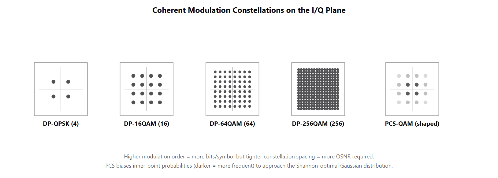
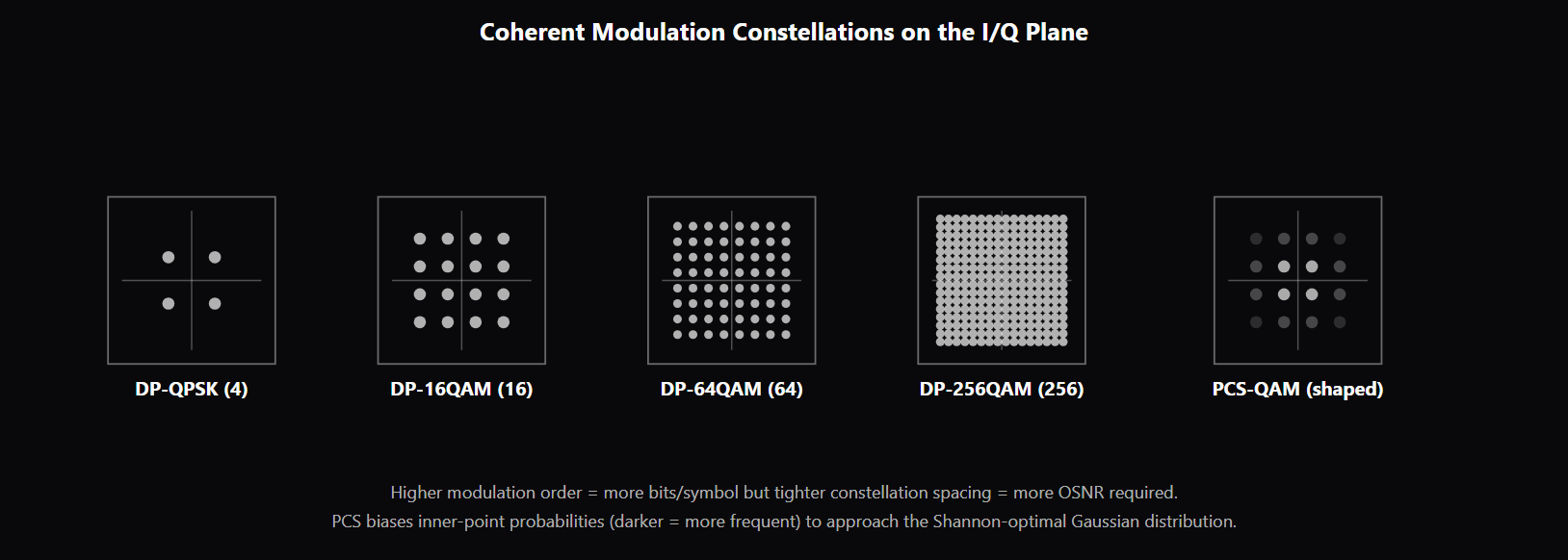
Coherent modulation formats are the encoding schemes that map user bits to constellation points on the I/Q plane of the optical field. The "DP" prefix means Dual-Polarization — the transmitter modulates both orthogonal polarizations of the carrier independently, doubling the data rate compared to a single-polarization version. The modulation order names the number of constellation points per polarization: QPSK has 4 (2 bits/symbol/pol), 16QAM has 16 (4 bits), 64QAM has 64 (6 bits), 256QAM has 256 (8 bits). Each step up the modulation order doubles the bits per symbol but roughly doubles the OSNR margin needed because constellation points move closer together. Line-rate math has four multiplicative factors: baud rate × bits per symbol per polarization × number of polarizations (2 for DP) × FEC-overhead factor. A 64 GBaud DP-16QAM channel with 20% FEC overhead has gross line rate 64 × 4 × 2 = 512 Gb/s and net payload 512 / 1.20 = ~427 Gb/s. Marketing names like "400G" refer to net payload after FEC overhead. The same physical transceiver can carry different net payloads by selecting different FEC profiles — higher overhead for harder routes, lower for easier ones. Probabilistic Constellation Shaping (PCS) is the architectural advance that lets coherent transceivers approach the Shannon capacity limit (see /topics/communication-systems) for AWGN channels. PCS keeps the QAM constellation grid but biases the symbol-selection probabilities so inner (low-power) symbols are sent more often than outer (high-power) symbols, approaching the Gaussian-shaped distribution that is capacity-optimal. The gain is 1.0–1.5 dB of effective OSNR at the same line rate compared to uniform QAM. The killer feature is rate-adaptivity: by varying the shaping aggressiveness, the same physical transceiver produces a continuous range of net payloads matched to the route's OSNR margin, instead of being stuck on the discrete (DP-QPSK, DP-16QAM, DP-64QAM) ladder. Nyquist pulse shaping is the spectral-efficiency mechanism on the transmitter side. Coherent transmitters apply root-raised-cosine (RRC) pulse shaping with low roll-off (typically 0.1–0.2) to confine each channel's spectrum close to the baud rate. Lower roll-off packs channels closer together in DWDM, enabling near-Nyquist channel spacing in flex-grid systems and superchannel sub-carrier arrangements. The cost is sharper filter design in transmit DSP and increased sensitivity to filter cascades through ROADMs. The combination of Nyquist pulse shaping at the transmitter and near-Nyquist channel spacing at the system level is what enables the high spectral efficiencies of modern 400G+ DWDM. The OSNR-reach-capacity trade-off is the fundamental optical-transport design choice (see /topics/osnr-ber-q-factor). Higher-order modulations carry more bits per symbol but need more OSNR. Higher FEC overhead provides more correction margin but reduces net payload. PCS adds a continuous tuning lever between these extremes. Operators size the choice per route: submarine and long-haul use DP-QPSK with strong FEC; metro DCI uses DP-16QAM or DP-64QAM with lighter FEC; very short DCI uses DP-64QAM or DP-256QAM with PCS at high baud rates. The same transceiver platform supports the full range by selecting the operating point per channel.
Why interviewers ask
Coherent modulation formats are the most-asked topic in coherent-transceiver and optical-transport interviews because the choice of format, FEC overhead, and shaping is the central capacity-versus-OSNR design lever — and the candidate has to be able to navigate it. A candidate who fluently calculates line rate, distinguishes net from gross, knows when each format wins, and understands PCS and Nyquist pulse shaping is showing the integrated coherent-system understanding that senior transceiver and transport roles (see /topics/optical-engineer-interview-signals) require. The line-rate math is the diagnostic question. Strong candidates can compute (baud × bits/symbol/pol × 2 × FEC) without thinking and explain which is gross vs net; weak candidates either get confused on the four factors or treat baud rate and bit rate as interchangeable. PCS is the most-asked architectural-advance question for any candidate claiming familiarity with modern coherent. Strong candidates explain that PCS biases symbol-selection probabilities to approach the Gaussian-optimal distribution, recovers 1.0–1.5 dB of effective OSNR at the same rate, and is rate-adaptive (the killer feature). Weak candidates name PCS but cannot describe what it shapes or what advantage it gives. The OSNR-reach-capacity trade-off is the senior-level systems question. Candidates who can connect modulation-order choice to OSNR margin to reach to FEC overhead and explain how operators tune per route are showing deployment experience; candidates who treat each parameter in isolation have not faced production transceiver configuration. Nyquist pulse shaping is the spectral-efficiency question. Candidates who explain that RRC with low roll-off is the mechanism for packing channels closer together in DWDM (and the cost is sharper filter design and ROADM-cascade sensitivity) reveal exposure to flex-grid operations. Candidates who do not name Nyquist shaping at all miss a major piece of the coherent-transmitter design.
Common mistakes
The most common mistake is treating line rate as one number. The four multiplicative factors (baud × bits/symbol/pol × polarizations × FEC) all matter, and candidates who collapse them miss the relationship. Strong candidates can decompose any quoted transceiver rate into these factors and back-calculate the FEC profile. A second gap is confusing gross with net. Marketing "400G" refers to net payload after FEC overhead is subtracted, but engineering line rate often refers to gross (before FEC). Candidates who do not distinguish the two miss specs, miscalculate margins, and confuse operations. A third gap is missing PCS. Some candidates know DP-QPSK, DP-16QAM, DP-64QAM as a fixed ladder and do not understand that PCS makes the ladder continuous. Other candidates name PCS but do not understand the mechanism (biasing symbol probabilities toward inner constellation points to approach the Gaussian-optimal distribution). Strong candidates know both the mechanism and the rate-adaptivity benefit. A fourth gap is treating modulation order as the only OSNR knob. Higher-order modulations need more OSNR, yes — but PCS provides 1.0–1.5 dB of gain at the same rate, FEC overhead provides additional margin in exchange for net payload, and Nyquist pulse shaping affects the spectral footprint independently of modulation order. Coherent transceiver design has multiple knobs; candidates who reduce it to "pick a modulation" miss the design surface. A fifth gap is missing Nyquist pulse shaping. Some candidates assume coherent transmitters use rectangular pulses; they do not — they use RRC with low roll-off. The roll-off factor affects spectral footprint and ROADM-cascade sensitivity. Candidates who do not surface pulse shaping have not worked at the DSP-transmitter level. See /topics/coherent-optical-detection for the receiver-side architecture, /topics/dwdm-systems-explained for the channel-planning context, /topics/mach-zehnder-modulators-and-vpi for the transmitter modulator architecture, and /topics/edfa-vs-raman-vs-soa for the OSNR-cascade budget that constrains modulation-order choice.
Coherent Modulation Formats — Capacity and OSNR Trade-offs
| Format | Bits/symbol/pol | Bits/symbol total | OSNR required (rel. DP-QPSK) | Typical use |
|---|---|---|---|---|
| DP-QPSK | 2 | 4 | Baseline (lowest) | Long-haul, submarine, very long reaches |
| DP-8QAM | 3 | 6 | ~3 dB more | Niche; less common than 16QAM |
| DP-16QAM | 4 | 8 | ~6–7 dB more | 200G–400G workhorse for metro/DCI |
| DP-32QAM / DP-64QAM | 5 / 6 | 10 / 12 | ~10–13 dB more | 400G–800G shorter-reach metro/DCI |
| PCS-QAM (rate-adaptive) | ~3.5–7 (tunable) | ~7–14 | Variable; ~1.5 dB advantage vs uniform | Most modern 400ZR+/800ZR transceivers |
| DP-256QAM | 8 | 16 | ~16–18 dB more | 1.6T short-reach |
Sample interview questions
- A 400G coherent transceiver runs DP-16QAM at 64 GBaud with 20% FEC overhead. What is the gross line rate, the net payload rate, and what does each rate include or exclude?
- A. Gross line rate equals net payload rate; FEC overhead does not change the rate.
- B. Gross line rate = 64 GBaud × log2(16) × 2 polarizations = 512 Gb/s — the total bits including FEC overhead. Net payload rate = 512 Gb/s ÷ 1.20 = ~427 Gb/s — the user-payload bits after FEC overhead is subtracted. Marketing "400G" usually refers to the net payload rate (or a rounded version thereof), not the gross line rate. Higher FEC overhead trades net payload for OSNR margin; lower overhead does the opposite. ✓
- C. Gross line rate = 400 Gb/s; FEC overhead is a separate side channel.
- D. The rates depend only on baud rate, not on modulation order or polarizations.
Option B is correct. Coherent line-rate math has four multiplicative factors: - Baud rate (symbol rate): 64 GBaud - Bits per symbol per polarization: log2(modulation_order) = log2(16) = 4 for DP-16QAM - Polarizations: 2 (the "DP" in DP-16QAM) - FEC overhead: divides net payload by (1 + overhead_fraction) For this example: - Gross line rate = 64 GBaud × 4 bits/symbol × 2 polarizations = 512 Gb/s - Net payload = 512 / 1.20 = ~427 Gb/s (or ~400G if FEC overhead is 28%) The "400G transceiver" naming refers to net payload, the user-data rate after FEC overhead is subtracted. The same physical transceiver could carry different net payloads depending on the FEC profile selected: - 14% overhead → 449 Gb/s net (less OSNR margin) - 20% overhead → 427 Gb/s net (moderate margin) - 28% overhead → 400 Gb/s net (strong margin) Operators select the FEC profile per route based on the OSNR available and the reach required. A submarine route with tight OSNR uses a high-overhead FEC; a metro DCI route with comfortable OSNR uses lower overhead and gets more net payload. Option A is wrong — FEC absolutely changes net payload. Option C confuses gross and net; FEC is in-band redundancy, not a side channel. Option D is wrong — line rate has four factors, not just baud. Production reality: coherent transceivers expose multiple FEC profiles selectable per channel; operators tune the choice to the route's OSNR budget and desired margin.
- What is probabilistic constellation shaping (PCS) and what does it gain over fixed-modulation QAM?
- A. PCS is a different modulation order than QAM; it has nothing to do with how symbols are selected.
- B. PCS keeps the QAM constellation grid but biases the symbol-selection probabilities so inner (low-power) symbols are sent more often than outer (high-power) symbols. This approaches the Shannon-capacity-optimal distribution (which is Gaussian-shaped, not uniform), recovering 1.0–1.5 dB of effective OSNR gain at the same line rate compared to uniform QAM. PCS is rate-adaptive: by adjusting the shaping aggressiveness, the same physical transceiver can produce a smooth range of net payloads matched to the route's OSNR margin, instead of being stuck on the discrete (DP-QPSK, DP-16QAM, DP-64QAM) ladder. ✓
- C. PCS only works with direct detection, not coherent.
- D. PCS is mathematically equivalent to uniform QAM; the naming is marketing.
Option B is correct. PCS (Probabilistic Constellation Shaping) is the technique that lets coherent transceivers approach the Shannon capacity limit for AWGN channels. The intuition: for an AWGN channel with a peak-power constraint, the capacity-optimal input distribution is approximately Gaussian — sending each amplitude proportional to a Gaussian PDF. Uniform QAM (where each constellation point is sent with equal probability) falls about 1.5 dB short of the Shannon limit. PCS biases the symbol probabilities so inner (low-power) symbols are sent more often than outer (high-power) symbols, approaching the Gaussian distribution. Practically: - PCS uses a distribution matcher (typically constant-composition) that translates a uniform-distributed input bit stream into a shaped symbol stream - The receiver-side inverse distribution matcher recovers the bits - The shaping aggressiveness is a tunable parameter — more shaping gets closer to Shannon but reduces the effective information rate The OSNR gain at the same line rate is 1.0–1.5 dB depending on the modulation order; equivalently, at the same OSNR you can carry 0.4–0.7 bits/symbol more. The killer feature is rate-adaptivity: by varying the shaping aggressiveness, the same transceiver produces a continuous range of net payloads (instead of being stuck at the discrete DP-QPSK → DP-16QAM → DP-64QAM ladder). Operators can fit the transceiver capacity to the route's OSNR exactly. Option A misses that PCS is about symbol-probability selection on a QAM grid. Option C is wrong — PCS is a coherent-only technique. Option D dismisses real capacity gains as marketing. Production reality: PCS is standard in 400ZR+, 800ZR, and most modern long-reach coherent transceivers. It is one of the architectural advances that makes 1.6T coherent practical in deployable OSNR budgets.
- What is Nyquist pulse shaping and why is it used in coherent transmitters?
- A. Nyquist pulse shaping is identical to rectangular pulse shaping; the naming is historical.
- B. Nyquist pulse shaping uses a raised-cosine (or root-raised-cosine) pulse shape with low roll-off to confine each symbol's spectrum close to the baud rate (theoretically baud-rate-equal spectral occupancy for zero roll-off). This packs channels closer together in the frequency domain than the wider sinc-shaped or rectangular alternatives, enabling more channels per fiber in DWDM systems and superchannel sub-carriers. Practical roll-off factors are 0.1–0.2 (10–20% extra spectrum) to balance ICI suppression against sharp filter implementation cost. ✓
- C. Nyquist pulse shaping requires more transmit power than rectangular pulses.
- D. Nyquist pulse shaping only applies to direct-detection systems.
Option B is correct. The Nyquist criterion specifies that a baud-rate signal can be transmitted with zero inter-symbol interference (ISI) using a pulse shape whose spectrum is rectangular (sinc in time). The ideal Nyquist pulse has spectrum occupancy exactly equal to the baud rate (sometimes called "Nyquist bandwidth"), which is the theoretical minimum spectrum needed. In practice, coherent transmitters use root-raised-cosine (RRC) pulse shaping with a low roll-off factor (typically 0.1–0.2). RRC is a practical approximation of the ideal Nyquist pulse: - Roll-off 0 = ideal rectangular spectrum (perfect bandwidth efficiency but unrealizable) - Roll-off 0.1 = 10% extra spectrum (1.1× baud rate); near-Nyquist with practical filters - Roll-off 0.2 = 20% extra spectrum; common production choice - Roll-off 0.5 or higher = older, less spectrally efficient Lower roll-off means tighter spectrum, more channels per band, and more usable capacity in flex-grid systems. The cost is sharper filter design (more filter taps in DSP), and increased sensitivity to filter cascades through ROADMs (each WSS adds some passband-shape roll-off). Why this matters: at 64 GBaud with roll-off 0.1, the channel's spectral footprint is about 70 GHz; in a 50 GHz fixed-grid slot it overlaps with neighbors. In a flex-grid system with 12.5 GHz slot granularity, the channel is allocated 6 slots (75 GHz) which fits. Higher baud rates require either flex-grid or wider fixed-grid slots, and the roll-off factor is the lever that adjusts the spectrum-vs-implementation trade-off. Option A misses that Nyquist pulse shaping is the spectrally-efficient design vs the wider-spectrum alternatives. Option C is wrong — Nyquist shaping does not change transmit power; it shapes spectrum. Option D is wrong — Nyquist applies to coherent systems where the receiver can match-filter the shape; direct-detection uses different pulse shapes. Production reality: every coherent transceiver does Nyquist pulse shaping in transmit-side DSP. The roll-off factor is configurable; operators trade roll-off against system tolerance to filter cascades.
Frequently asked questions
- What are coherent modulation formats?
- Coherent modulation formats encode information in the full complex baseband — both amplitude and phase, in both orthogonal polarizations — of an optical carrier. The format names follow a standard pattern: "DP-XQAM" means "Dual-Polarization X-QAM," where X is the modulation order per polarization. DP-QPSK carries 2 bits per polarization per symbol (4 bits total per symbol across both polarizations). DP-16QAM carries 4 bits per polarization (8 total). DP-64QAM carries 6 bits per polarization (12 total). DP-256QAM carries 8 bits per polarization (16 total). Each step up the modulation order doubles the data per symbol but roughly doubles the required OSNR margin, so format selection is fundamentally an OSNR-versus-rate trade-off.
- How is coherent line rate calculated?
- The gross line rate is the product of four factors: baud rate × bits per symbol per polarization × number of polarizations × FEC overhead factor. For a 400G transceiver at 64 GBaud DP-16QAM with 20% FEC overhead: gross line rate = 64 GBaud × 4 bits × 2 polarizations = 512 Gb/s; net payload = 512 / 1.20 = ~427 Gb/s. The marketing "400G" refers to the net payload after FEC overhead is subtracted. The same physical transceiver can carry different net payloads by selecting different FEC profiles — higher overhead for harder routes, lower overhead for easier ones.
- What is DP-QPSK?
- DP-QPSK (Dual-Polarization Quadrature Phase Shift Keying) sends 2 bits per polarization per symbol — 4 bits total per symbol across both polarizations. The constellation has 4 points per polarization arranged at the corners of a square, with all points equidistant from the origin (constant modulus, which helps the CMA polarization-demultiplexing algorithm). DP-QPSK was the format that launched 100G coherent transmission around 2010 at 32 GBaud (giving 100G gross, ~100G net after early FEC). It is still the format of choice for the longest unregenerated reaches because its constellation cleanliness gives the lowest OSNR threshold of any common coherent format.
- When is DP-16QAM vs DP-64QAM the right choice?
- DP-16QAM carries 4 bits per polarization per symbol (8 total); DP-64QAM carries 6 bits (12 total) — a 1.5× capacity gain at the same baud rate. The trade-off is OSNR: DP-64QAM constellation points are closer together, so it needs roughly 6–7 dB more OSNR for the same BER. DP-16QAM is the workhorse for 200–400G coherent at 32–64 GBaud, used on most terrestrial DWDM and DCI routes where OSNR budgets are comfortable. DP-64QAM is used at shorter reaches where the OSNR budget can support it — metro and DCI under 200 km — and now in 800G+ transceivers where the higher baud rate × DP-64QAM combination produces 800G–1.2T per channel. Above DP-64QAM, DP-256QAM (8 bits per polarization, 16 total) starts appearing in 1.6T-class transceivers at very short reaches.
- What is probabilistic constellation shaping (PCS)?
- PCS biases the symbol-selection probabilities on a QAM constellation so that inner (low-power) symbols are sent more often than outer (high-power) symbols. This approaches the Gaussian distribution that is theoretically capacity-optimal for AWGN channels, recovering 1.0–1.5 dB of effective OSNR gain at the same line rate vs uniform QAM. PCS is rate-adaptive: by varying the shaping aggressiveness, the same physical transceiver produces a continuous range of net payloads matched to the route's OSNR margin, instead of being stuck on discrete modulation steps. PCS is standard in 400ZR+, 800ZR, and most modern long-reach coherent transceivers — one of the architectural advances that made 1.6T coherent practical.
- What is Nyquist pulse shaping?
- Nyquist pulse shaping uses root-raised-cosine (RRC) pulse shapes with low roll-off to confine each symbol's spectrum close to the baud rate. The ideal Nyquist pulse occupies spectrum exactly equal to the baud rate (rectangular spectrum); practical RRC uses roll-off 0.1–0.2 (10–20% extra spectrum). Lower roll-off packs channels closer together in DWDM, enabling superchannel sub-carrier spacings near the Nyquist limit. The cost is sharper filter design in transmit-side DSP and increased sensitivity to filter cascades through ROADMs. Every modern coherent transmitter does Nyquist pulse shaping; the roll-off is a configurable parameter operators tune to the route's ROADM cascade.
- What is the OSNR-reach-capacity trade-off?
- The fundamental trade-off in coherent transmission is between modulation order (capacity), FEC overhead (margin), and OSNR available (route quality). Higher-order modulations carry more bits per symbol but need more OSNR. Higher FEC overhead provides more correction capability (more OSNR margin) but reduces net payload. The OSNR a route provides is set by amplifier noise, span count, fiber type, and nonlinear effects. Operators size the choice per route: long-haul submarine routes use DP-QPSK with strong FEC (~25–30% overhead); metro DCI uses DP-16QAM or DP-64QAM with lighter FEC; very short DCI uses DP-64QAM or PCS-QAM at high baud rates. The same transceiver platform supports a range of these operating points by selecting the modulation order and FEC profile per channel.
- What is Nyquist WDM (N-WDM)?
- Nyquist WDM packs DWDM channels (or superchannel sub-carriers) at spacing equal to the baud rate — the minimum spacing the Nyquist criterion allows for zero ICI. For example, four 32-GBaud sub-carriers spaced at 32 GHz produce a superchannel with no spectral gap between sub-carriers. N-WDM is the design that maximizes spectral efficiency at the cost of strict filter and synchronization requirements. Practical N-WDM systems leave a small margin above strict-Nyquist spacing (typically 1–5%) to absorb filter-cascade penalties through ROADMs. The combination of Nyquist pulse shaping at the transmitter plus near-Nyquist channel spacing at the system level is what enables the high spectral efficiencies of modern superchannels.
Related topics
Siblings
- Coherent Optical Detection: How DSPs Replaced Direct Detection
- OSNR, BER, Q-factor: How Optical Engineers Measure Link Quality
- DWDM Systems Explained: C-Band, L-Band, and the 400G/800G Era
- Mach-Zehnder Modulators Explained: Vπ, Chirp, and Bias
- Optical Fiber Impairments Explained: CD, PMD, Nonlinearity
- Optical Engineer Interview Signals: What Interviewers Probe
Essential AI-Native Skills for Coherent Modulation Formats: DP-QPSK, 16QAM, PCS Explained
Modern engineering work increasingly uses AI tools for design and code review, debugging, documentation, test and testbench generation, and workflow automation. The goal is not to let AI replace engineering judgment — it is to move faster while keeping verification discipline.
- Use AI to explain unfamiliar code, logs, waveforms, datasheets, or test failures.
- Break large problems into small, reviewable steps you can verify independently.
- Ask AI for hypotheses, then validate them against tests, measurements, simulations, or lab data.
- Version-control your analysis scripts, testbenches, and configs — keep changes small and reviewable.
- Document your assumptions, design tradeoffs, and debugging decisions.
- Verify AI output before trusting it: run the checks that fit the domain — unit tests, linters, simulations, or bench/lab measurements.
- Review AI output for correctness, edge cases, and real-world consequences.
Coherent Modulation Formats: DP-QPSK, 16QAM, PCS Explained — coming to the question bank
The adaptive practice engine is already live for core wireless, RF, and ML systems. Coherent Modulation Formats: DP-QPSK, 16QAM, PCS Explained isn't covered in the question bank yet — get notified when it's added.