Coherent Optical Detection: How DSPs Replaced Direct Detection Interview Prep
Coherent optical detection explained — local oscillator, 90° hybrid, balanced photodiodes, DSP pipeline, LO linewidth, and intradyne reception.
Quick answer
Coherent optical detection is the architectural shift that replaced direct detection across long-haul, metro, and DCI optical links between roughly 2010 and 2020 — and is now extending into ever-shorter reaches as silicon-photonics integration drives down its cost.
Coherent detection is the most-asked single architectural topic in optical-engineering interviews because it integrates optical physics, DSP, FEC, and silicon implementation into one system that the candidate has to be able to describe from the receive optical hybrid through the soft-decision FEC decoder.
Editorial review
Written by
CompoundLearn editorial team
Wireless / RF / hardware engineering
Reviewed by
CompoundLearn editorial team
Wireless / RF / hardware engineering
Last reviewed
Built from curated topic maps, editorial validation, and subject-matter review so the page stays aligned with the interview intent and the current content pipeline.
What it is
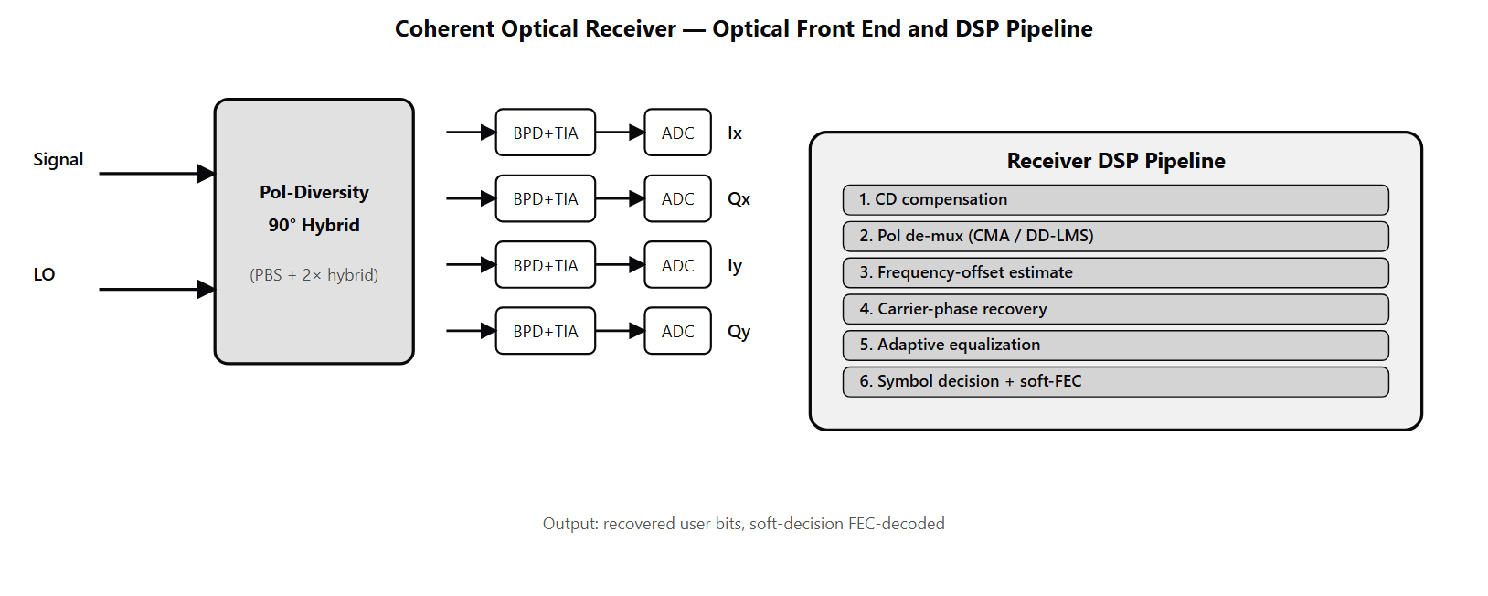
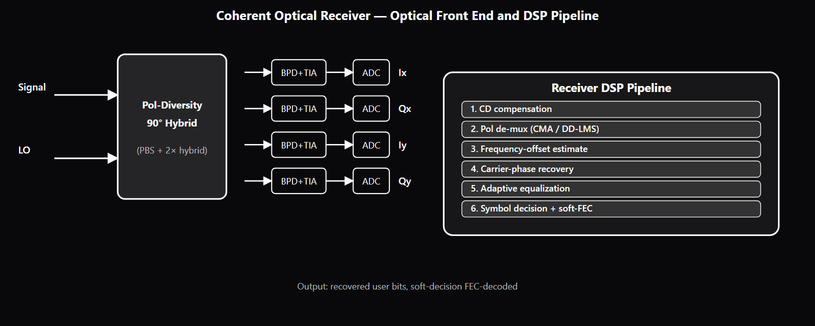
Coherent optical detection is the architectural shift that replaced direct detection across long-haul, metro, and DCI optical links between roughly 2010 and 2020 — and is now extending into ever-shorter reaches as silicon-photonics integration drives down its cost. The defining feature is that a coherent receiver mixes the incoming signal with a local-oscillator (LO) laser before photodetection, recovering the full complex baseband — amplitude and phase, in both orthogonal polarizations — instead of the intensity-only measurement direct detection produces. The optical front end of a coherent receiver is built around the 90° optical hybrid. The hybrid takes signal and LO as inputs and produces four output ports with phase shifts of 0°, 90°, 180°, and 270° between them. Balanced photodetection across the (0°, 180°) pair gives the in-phase electrical stream; balanced photodetection across the (90°, 270°) pair gives the quadrature stream. A polarization-diversity arrangement uses a polarization beam splitter to separate the two orthogonal polarizations and a 90° hybrid for each, yielding four output streams: I_x, Q_x, I_y, Q_y. These are digitized by high-speed ADCs (typically 56+ GSa/s per channel for 60 GBaud signaling) and handed to the receiver DSP. The receiver-side DSP is the largest block of silicon in a coherent transceiver — billions of gates of fixed-function logic plus configurable adaptive filters. The block pipeline runs in a specific order because each block assumes the prior stages have been compensated. Chromatic-dispersion compensation comes first — even moderate links accumulate enough dispersion that each symbol spreads across many neighbors, and the equalizer must remove this before subsequent stages can converge. Polarization de-multiplexing follows, typically using CMA (Constant Modulus Algorithm) for fixed-modulus formats or DD-LMS variants for QAM, to untangle the two polarization streams the transmitter polarization-multiplexed. Frequency-offset estimation removes the multi-GHz offset between LO and transmitter laser. Carrier-phase recovery (Viterbi-Viterbi for QPSK; Blind Phase Search for QAM) tracks residual phase drift. Adaptive equalization handles residual ISI and some mild nonlinear effects. Symbol decision and soft-decision FEC decoding (typically LDPC) produce the recovered bits. Most production coherent receivers operate as intradyne rather than strict homodyne or heterodyne. The LO is approximately matched to the signal carrier with a residual offset of a few GHz, and the DSP estimates and removes this offset digitally. The intradyne approach avoids the optical phase-locked loop that strict homodyne would require, while keeping the IF bandwidth small enough for tractable ADC and DSP design. This is the architectural choice that made practical 100G+ coherent transceivers possible. LO linewidth — the spectral width of the LO laser carrier — is one of the binding constraints on coherent transceiver design. The narrower the linewidth, the less phase noise on the signal-LO mixed product, and the higher the modulation order that DSP phase recovery can support. Modern coherent transceivers use external-cavity lasers (ECL) with sub-100-kHz linewidth as the baseline; DP-64QAM operation at 60–100 GBaud requires sub-100-kHz linewidth, and DP-256QAM (used in some 1.6T configurations) needs sub-10-kHz linewidth, often from integrated narrow-linewidth lasers with master-oscillator injection locking.
Why interviewers ask
Coherent detection is the most-asked single architectural topic in optical-engineering interviews because it integrates optical physics, DSP, FEC, and silicon implementation into one system that the candidate has to be able to describe from the receive optical hybrid through the soft-decision FEC decoder. A candidate who fluently walks through the 90° hybrid, balanced photodetection, polarization diversity, the DSP pipeline in order, frequency-offset estimation, and carrier-phase recovery is showing the integrated understanding that staff and principal optical-engineer roles require. Hiring teams probe the 90° hybrid specifically because the design rationale is non-obvious. Strong candidates explain that the hybrid produces the four ports with 0°/90°/180°/270° relationships needed for balanced I and Q recovery; weak candidates name the hybrid without explaining what would be lost without it (the entire phase information, collapsing the receiver to direct detection). The DSP pipeline order is the diagnostic question. Candidates who name the blocks in the wrong order — for example, putting phase recovery before dispersion compensation — reveal that they have not thought through the dependency structure. The correct order (CD → pol de-mux → frequency offset → phase recovery → equalization → decision) reflects the fact that each block assumes the prior stages have been compensated. LO linewidth is the deep-cut topic. Candidates who know the formula (phase-noise variance ≈ linewidth × symbol_duration) and can connect it to the achievable modulation order have studied coherent in depth; candidates who name linewidth as a spec without understanding why it bounds modulation order have not yet built the connection. The phase-recovery-algorithm limit (~10⁻⁴ rad² variance per symbol) is a senior-level number. The direct-detection-vs-coherent boundary is probed because operational engineers need to know when each is appropriate. Strong candidates explain that short-reach datacenter links still favor IM-DD due to cost, that the crossover point shifts as SiPh drives down coherent transceiver cost, and that all long-haul / DCI / metro applications are now coherent. Weak candidates dismiss direct detection as obsolete or fail to identify when it still wins.
Common mistakes
The most common mistake is describing coherent detection as "just a fancier photodiode." The architectural shift from direct detection to coherent is the move from intensity-only reception to full complex-baseband recovery, enabled by the 90° hybrid and LO. Candidates who miss this collapse the entire architectural distinction. A second gap is missing the DSP pipeline order. The correct sequence — chromatic dispersion compensation → polarization de-multiplexing → frequency-offset estimation → carrier-phase recovery → equalization → decision — is determined by the dependency structure of the impairments. Candidates who order phase recovery before dispersion compensation have not understood that dispersion smears symbols across many neighbors and must be removed before per-symbol algorithms can converge. A third gap is misunderstanding LO linewidth. Some candidates think linewidth affects only the optical power budget (it does not — linewidth converts to phase noise on the mixed product, which costs SNR via the constellation rather than power). Some claim DSP can compensate any linewidth (it cannot — there is a phase-noise-variance ceiling above which phase recovery fails). Strong candidates know the rough numbers: kHz-class linewidth required for DP-16QAM, tens-of-kHz for DP-64QAM, sub-10-kHz for DP-256QAM at typical baud rates. A fourth gap is confusing intradyne with homodyne or heterodyne. Strict homodyne (LO exactly locked to signal) requires an optical phase-locked loop, which is impractical at production scale. Strict heterodyne (large IF offset) costs ADC bandwidth. Intradyne (LO approximately matched, residual offset removed in DSP) is the practical choice; candidates who do not name intradyne or who treat all three as equivalent miss the architectural decision that made coherent practical. A fifth gap is missing the direct-detection vs coherent application boundary in 2026. Short-reach datacenter links are still cheaper with IM-DD PAM-4 or PAM-6; long-haul, metro, and DCI are all coherent. The crossover point is shifting as SiPh integration drives down coherent transceiver cost, with 1.6T datacenter links increasingly going coherent. Candidates who treat direct detection as obsolete miss the cost-versus-capacity trade-off that operators actually make.
Coherent vs Direct Detection — Capability and Cost Trade-offs
| Property | Direct Detection (IM-DD) | Coherent Detection |
|---|---|---|
| Recovered information | Intensity only (|E|²) | Full complex baseband (amplitude + phase, both polarizations) |
| Supported modulations | OOK, NRZ, PAM-4, PAM-6 | DP-QPSK, DP-16QAM, DP-64QAM, PCS-QAM |
| Reach | Short (~100 m to ~2 km for 100G–200G) | Metro, DCI, regional, long-haul, submarine |
| Dispersion compensation | Optical (DCF) or limited reach | DSP-based, scalable to thousands of km |
| Required components | Photodiode + TIA + ADC | 90° hybrid + balanced PDs + LO laser + pol-diversity optics + ADCs + DSP |
| Cost / power per Gb/s | Lower (short reach) | Higher but converging via SiPh integration |
Sample interview questions
- A coherent optical receiver requires a 90° optical hybrid in front of the balanced photodiodes. Why is the 90° hybrid specifically necessary, and what would be lost if a simple beam combiner were used?
- A. The 90° hybrid only improves SNR; a beam combiner would work but with a 3 dB penalty.
- B. The 90° hybrid produces four output ports with specific phase relationships (0°, 90°, 180°, 270°) of the signal-plus-LO mix, which the balanced photodiode pairs convert into separate I and Q electrical streams. Without the 90° hybrid the receiver still beats the signal against the LO on a single port, but it recovers only one quadrature (a single I-or-Q projection) and cannot separate I from Q — which kills DP-QPSK and all higher-order coherent formats. ✓
- C. The 90° hybrid is only required when the LO and signal are exactly co-polarized.
- D. The 90° hybrid is interchangeable with a Mach-Zehnder modulator; either device works in the receiver.
Option B is correct. A coherent receiver needs to recover both the in-phase (I) and quadrature (Q) components of the received optical field — that is what makes "coherent" coherent. The 90° optical hybrid takes the signal and the LO as inputs and produces four output ports with phase shifts of 0°, 90°, 180°, 270° between them. Balanced photodetection across the (0°, 180°) pair gives the I component; balanced photodetection across the (90°, 270°) pair gives Q. The result is the receiver outputting two electrical streams that together carry the full complex baseband. Without the 90° hybrid (e.g., with a single 50:50 combiner and one balanced pair) the photocurrent is |E_sig + E_LO|² = |E_sig|² + |E_LO|² + 2·Re{E_sig·E_LO*}. The beat term 2·Re{E_sig·E_LO*} = 2|E_sig||E_LO|·cos(Δφ) is still present — so this is not direct detection (which has no LO at all) and phase is not lost outright. But a single port measures only that one in-phase projection; without the orthogonal 90°-shifted product you cannot recover the quadrature component, so you cannot separate I and Q. DP-QPSK, QAM, and every higher-order coherent format become unrecoverable. Polarization-diversity coherent receivers use two 90° hybrids (one per orthogonal polarization) plus polarization beam splitters, so the receiver recovers (I_x, Q_x, I_y, Q_y) — the full polarization-multiplexed complex field. Option A misses that the 90° hybrid is what enables coherent reception, not an SNR optimization. Option C is wrong — the 90° hybrid is required regardless of polarization; the polarization-diversity variant adds beam splitters around it. Option D confuses receiver and transmitter components — MZM is a transmitter modulator, not a receiver hybrid. Production reality: integrated coherent receivers (ICRs) and integrated coherent transceivers package the 90° hybrid, balanced PDs, TIAs, and ADC interfaces into one module; the hybrid is the heart of the optical front end.
- A coherent receiver-side DSP processes received samples through several blocks. What is the correct ordering of the major blocks, and why does the order matter?
- A. Carrier phase recovery → chromatic-dispersion compensation → polarization de-multiplexing → equalization → decision.
- B. Chromatic-dispersion compensation → polarization de-multiplexing (often via CMA) → frequency-offset estimation → carrier-phase recovery → equalization → decision. The order matters because each block assumes the prior stages have been compensated: dispersion is a large-scale linear impairment that dominates the channel response and must be removed first; polarization de-mux works on the dispersion-compensated stream; frequency offset and phase recovery only work once polarization is separated. ✓
- C. The blocks can run in any order — the DSP is associative.
- D. Equalization → decision → carrier-phase recovery → chromatic-dispersion compensation.
Option B is correct. The receiver-side DSP pipeline order is determined by the dependency structure of the impairments. Chromatic dispersion is a large linear impairment — even a moderate-length link accumulates dispersion that spreads each symbol across tens or hundreds of neighbors, so it has to be compensated first; subsequent stages assume the channel is approximately memoryless. Polarization de-multiplexing (CMA — Constant Modulus Algorithm — for fixed-modulus formats, or DD-LMS variants for QAM) untangles the two polarization streams that the transmitter polarization-multiplexed; this works on the dispersion-compensated stream. Frequency-offset estimation comes next — the offset between LO and transmitter laser is up to a few GHz and must be removed before phase recovery. Carrier-phase recovery (Viterbi-Viterbi or BPS algorithms) corrects the residual LO phase drift; this works once the constellation is rotating at a known rate. Finally, equalization (adaptive feedforward + decision-feedback) and symbol decision produce the recovered bits. The order matters because each stage has a target SNR range it operates in and assumes the prior stages have done their job. Running phase recovery before dispersion compensation would see a smeared constellation rotating from LO drift on top of inter-symbol interference — impossible to converge. Option A inverts the order. Option C is wrong — DSP block ordering is critical, not arbitrary. Option D reverses the dependency chain entirely. Production reality: coherent DSP runs in the multi-billion-gate range and is the single largest piece of silicon in a coherent transceiver; block-ordering decisions and per-block algorithm choices are core IP differentiators between transceiver vendors.
- How does local-oscillator (LO) linewidth bound the achievable coherent modulation order?
- A. LO linewidth is irrelevant — coherent reception removes all phase noise digitally.
- B. LO linewidth × symbol duration sets the within-symbol phase noise. As modulation order increases, the constellation points get closer together and tolerate less phase noise. Below a few hundred kHz LO linewidth (using narrow-linewidth integrated lasers and DSP phase-recovery), DP-64QAM and higher are achievable; at MHz-level linewidth, the phase noise dominates and the constellation collapses past DP-16QAM. This is why coherent transceivers spec their lasers in tens-of-kHz linewidth and why integrated narrow-linewidth lasers are a critical component. ✓
- C. LO linewidth must be exactly zero for coherent reception to work at all.
- D. LO linewidth limits only the optical power budget, not the achievable modulation order.
Option B is correct. Linewidth is the spectral width of the laser carrier; it converts directly into phase noise on the received signal once the laser is heterodyne-mixed with the LO. The within-symbol phase noise variance is roughly proportional to (LO_linewidth + signal_linewidth) × symbol_duration. Higher-order modulations have constellation points closer together (a 64QAM point separation in phase is much smaller than DP-QPSK), so the same phase noise that is invisible to DP-QPSK can blur the 64QAM constellation past the decision boundary. The DSP phase-recovery algorithm (Viterbi-Viterbi for QPSK; BPS for QAM) can compensate phase noise up to a point — typical algorithms work up to ~10⁻⁴ rad² phase noise variance per symbol. Beyond that, the algorithm cannot keep up. For symbol rates around 60–100 GBaud, this translates roughly to a kHz-class LO linewidth requirement for DP-16QAM and below, a tens-of-kHz requirement at DP-64QAM, and below ~10 kHz at DP-256QAM. Modern coherent transceivers use external-cavity lasers (ECL) with sub-100-kHz linewidth, or integrated narrow-linewidth lasers (sometimes via injection locking from a master laser) when the deployment scale demands volume. Option A is wrong — phase recovery has limits. Option C is too strict; non-zero linewidth is fine, just bounded. Option D confuses two different optical budgets. Production reality: laser-vendor linewidth specs are one of the binding constraints on transceiver designs for 800G+ DP-64QAM operation; the laser cost is non-trivially driven by linewidth requirements.
Frequently asked questions
- What is coherent optical detection?
- Coherent detection is an optical-receiver architecture that mixes the incoming signal with a local-oscillator (LO) laser before photodetection, so the receiver can recover both the amplitude and the phase of the optical field (the full complex baseband). The optical front end uses a 90° optical hybrid to produce four output ports with specific phase relationships, balanced photodiodes for I and Q output streams, and a polarization-diversity arrangement to also separate the two orthogonal polarizations. The result is a full complex-baseband signal in each polarization that downstream DSP can process for modulation formats far beyond what direct detection supports — DP-QPSK, DP-16QAM, DP-64QAM, and higher with PCS.
- How does coherent detection differ from direct detection?
- Direct detection uses a single photodiode to measure |E_received|² — the intensity of the optical field. It is simple and cheap (no LO required, no 90° hybrid, no polarization-diversity optics) but can only see intensity-modulated signals. Coherent detection mixes the received signal with an LO laser through a 90° hybrid, recovering both amplitude and phase. This lets coherent receivers demodulate phase-modulated formats (QPSK, QAM), separate polarization-multiplexed signals, and digitally compensate chromatic dispersion and other linear impairments in the DSP. Direct detection still dominates in short-reach datacenter links (intensity-modulated direct-detection, IM-DD, with NRZ or PAM-4) where the cost-versus-capacity trade-off favors the simpler architecture; coherent dominates above 100 Gb/s line rates and at any reach beyond a few km.
- What does the receiver-side coherent DSP do?
- The receiver-side DSP takes the four sampled streams (I_x, Q_x, I_y, Q_y from the polarization-diversity coherent front end) and processes them through a pipeline: (1) chromatic-dispersion compensation (large linear filter equivalent to a frequency-domain phase rotation); (2) polarization de-multiplexing using CMA or DD-LMS variants to separate the two polarization streams; (3) frequency-offset estimation to remove the multi-GHz offset between LO and transmitter laser; (4) carrier-phase recovery (Viterbi-Viterbi for QPSK; BPS for QAM) to track residual LO phase drift; (5) adaptive equalization for residual ISI and nonlinear compensation; (6) symbol decision and soft-decision FEC decoding (typically LDPC-based). Together these blocks recover the transmitted bits at OSNR levels close to the Shannon limit for the chosen modulation and FEC.
- Why is a 90° optical hybrid required at the coherent receiver?
- The 90° hybrid produces four output ports with phase shifts of 0°, 90°, 180°, 270° between the signal and LO mixed products. Balanced photodetection across the (0°, 180°) pair recovers the in-phase component; balanced photodetection across the (90°, 270°) pair recovers the quadrature component. Together these give the full complex baseband. Without the 90° hybrid a coherent receiver could only measure |signal + LO|² (an intensity), which loses the phase information that coherent reception is supposed to recover. Integrated coherent receivers (ICRs) package the 90° hybrid, balanced photodiodes, TIAs, and ADCs into one module.
- What is local-oscillator linewidth and why does it bound modulation order?
- LO linewidth is the spectral width of the local-oscillator laser at the coherent receiver. The narrower the linewidth, the less phase noise the receiver sees on the signal-LO mixed product. Phase noise variance roughly scales as (LO_linewidth + signal_linewidth) × symbol_duration, and the receiver-side DSP phase-recovery algorithm can compensate phase noise only up to a bounded variance. Higher-order modulations have constellation points closer together in phase, so they require lower phase-noise tolerance and therefore narrower-linewidth lasers. Practical coherent transceivers operate with sub-100-kHz linewidth external-cavity lasers for DP-16QAM and higher; pushing to DP-256QAM (used in some 1.6T configurations) requires sub-10-kHz linewidth.
- What is homodyne vs heterodyne coherent reception?
- In a strict homodyne receiver the LO is locked exactly to the signal carrier frequency so the down-converted signal lands at DC. In heterodyne the LO is at a fixed offset (intermediate frequency, IF) from the signal, so the down-converted signal lands at IF and is then digitized and processed at IF in DSP. Most production coherent receivers operate as intradyne — the LO is approximately matched to the signal carrier with a residual offset of a few GHz, and the DSP estimates and compensates this offset digitally. Intradyne avoids the need for an optical phase-locked loop while keeping the IF bandwidth small enough for tractable ADC and DSP design. The intradyne approach plus DSP-based offset removal is what makes practical coherent transceivers work at line rates above 100G.
- When is direct detection still preferred over coherent at 2026?
- Direct detection still wins in short-reach intra-datacenter links where the cost and power penalty of a coherent transceiver is too high. At 100 m to 2 km reach with single-mode fiber, intensity-modulated direct-detection (IM-DD) with PAM-4 or PAM-6 modulation supports 100G–200G per lane at much lower transceiver cost and power than coherent. The crossover point shifts over time as silicon photonics drives down coherent transceiver cost — current trends push coherent into shorter reaches (1.6T datacenter links are increasingly coherent), but the cost gap below 500 m is still meaningful. For long-haul, metro, and DCI applications, coherent is the only option; direct detection cannot reach beyond a few km without significant power and complexity penalties.
- How does coherent detection enable DSP-based dispersion compensation?
- Once the coherent receiver has the full complex baseband, chromatic dispersion (CD) is a linear filter that can be inverted in the DSP via a matched frequency-domain phase rotation. The receiver knows or estimates the accumulated dispersion of the link (from training symbols or blind estimation) and applies the inverse filter before passing the stream to subsequent DSP blocks. This replaced the older approach of in-line dispersion-compensating fiber (DCF) — bulky, lossy, and reach-limited — with a software solution. Coherent DSP-based CD compensation works for thousands of km of accumulated dispersion in a single pass, and it is one of the architectural improvements that made the leap from 10G direct-detection to 100G+ coherent possible. See /topics/optical-fiber-impairments (queued) for the impairment-physics context.
Related topics
Siblings
- Coherent Modulation Formats: DP-QPSK, 16QAM, PCS Explained
- DWDM Systems Explained: C-Band, L-Band, and the 400G/800G Era
- OSNR, BER, Q-factor: How Optical Engineers Measure Link Quality
- Mach-Zehnder Modulators Explained: Vπ, Chirp, and Bias
- Optical Fiber Impairments Explained: CD, PMD, Nonlinearity
- Optical Engineer Interview Signals: What Interviewers Probe
- Silicon Photonics for Datacenters Explained: 800G+ Links
- CPO vs Pluggable Optics: Density, Power & AI-Cluster Trade-offs
- Silicon Photonics Engineer Interview Signals
Essential AI-Native Skills for Coherent Optical Detection: How DSPs Replaced Direct Detection
Modern engineering work increasingly uses AI tools for design and code review, debugging, documentation, test and testbench generation, and workflow automation. The goal is not to let AI replace engineering judgment — it is to move faster while keeping verification discipline.
- Use AI to explain unfamiliar code, logs, waveforms, datasheets, or test failures.
- Break large problems into small, reviewable steps you can verify independently.
- Ask AI for hypotheses, then validate them against tests, measurements, simulations, or lab data.
- Version-control your analysis scripts, testbenches, and configs — keep changes small and reviewable.
- Document your assumptions, design tradeoffs, and debugging decisions.
- Verify AI output before trusting it: run the checks that fit the domain — unit tests, linters, simulations, or bench/lab measurements.
- Review AI output for correctness, edge cases, and real-world consequences.
Coherent Optical Detection: How DSPs Replaced Direct Detection — coming to the question bank
The adaptive practice engine is already live for core wireless, RF, and ML systems. Coherent Optical Detection: How DSPs Replaced Direct Detection isn't covered in the question bank yet — get notified when it's added.