5G NR Architecture: NSA vs SA, CU/DU Split, and CA Interview Prep
5G NR architecture — NSA Option-3 EN-DC vs SA Option-2, dual connectivity, CU/DU split, F1 interface, carrier aggregation, and 5GC functions.
Quick answer
5G NR architecture is the system-level question that integrates radio-access design, core-network choice, and deployment migration into one operational decision.
5G architecture is the most-asked deployment-strategy interview question in cellular roles because it integrates every layer: radio access, core network, transport, mobility, dual connectivity.
Editorial review
Written by
CompoundLearn editorial team
Wireless / RF / hardware engineering
Reviewed by
CompoundLearn editorial team
Wireless / RF / hardware engineering
Last reviewed
Built from curated topic maps, editorial validation, and subject-matter review so the page stays aligned with the interview intent and the current content pipeline.
What it is
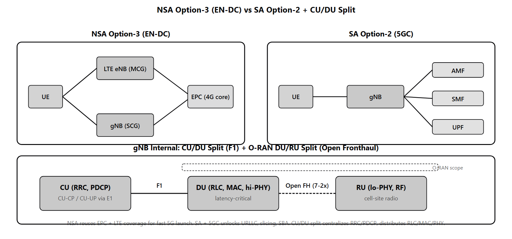
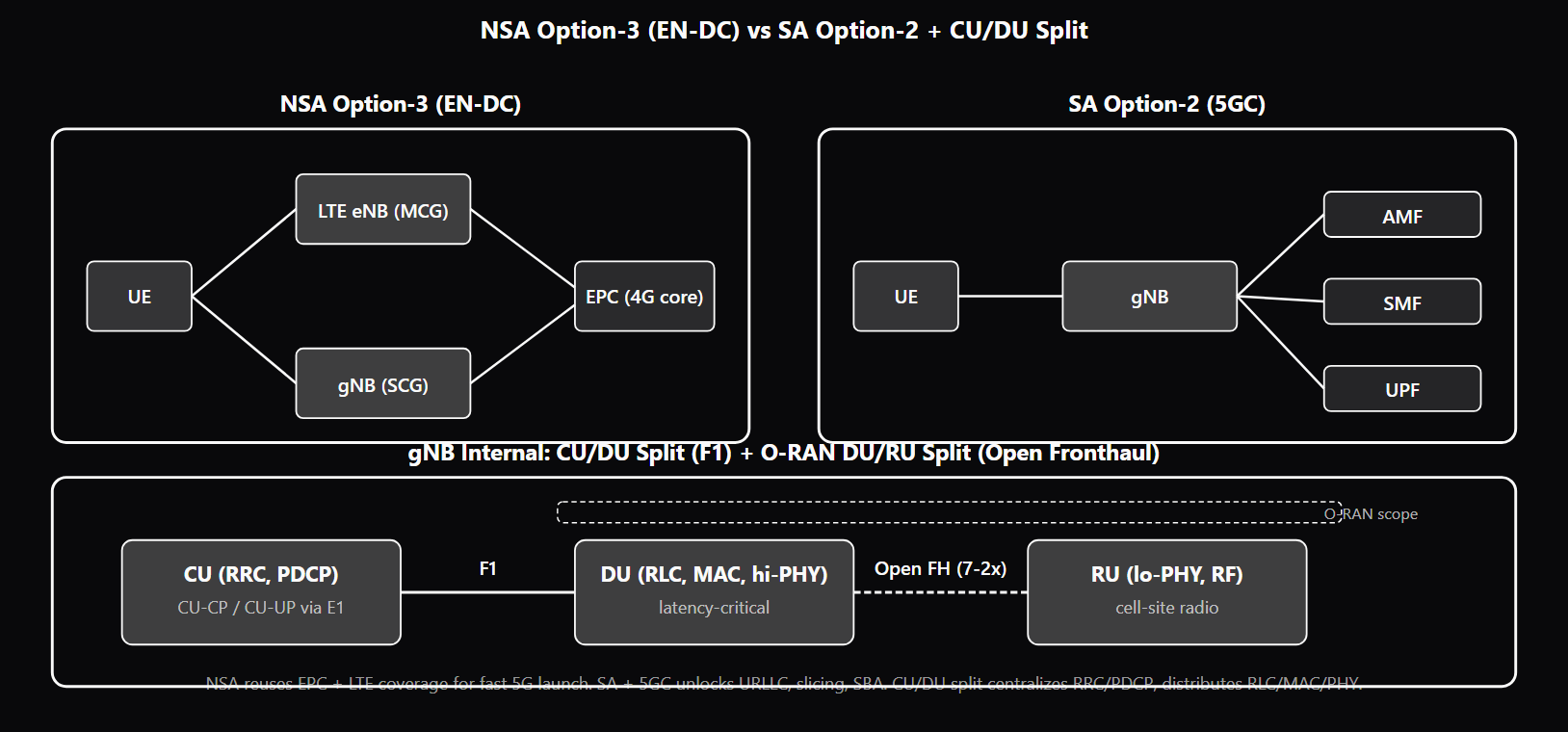
5G NR architecture is the system-level question that integrates radio-access design, core-network choice, and deployment migration into one operational decision. Operators choose architecture per deployment phase: NSA for initial 5G launches reusing existing LTE coverage and EPC core; SA for the full feature set including URLLC, slicing, and Service-Based Architecture. The CU/DU split adds an internal gNB structure that separates latency-critical from latency-tolerant layers, enabling centralized control and distributed radio. Carrier Aggregation aggregates multiple component carriers across bands to deliver peak throughput. Each of these architectural decisions has real cost, complexity, and feature-set implications. The NSA-vs-SA choice was the central deployment architecture for 5G operators from 2019 onward. NSA (Non-Standalone) Option-3 — also called EN-DC (E-UTRAN-NR Dual Connectivity) — keeps the EPC as the core, uses the LTE eNB as the Master Cell Group (MCG) anchoring RRC and mobility (see /topics/nr-rrc-states), and adds the gNB as a Secondary Cell Group (SCG) carrying high-throughput NR user-plane data. The UE is simultaneously connected to both nodes. NSA enabled operators to light up "5G" data services in months at a fraction of full-SA deployment cost, but cannot deliver URLLC, network slicing (see /topics/network-slicing-explained), Service-Based Architecture, or Voice over NR — features that require the 5GC. SA (Standalone) Option-2 replaces the EPC with the 5GC and uses the gNB alone for both control and user planes. The 5GC is built on Service-Based Architecture (HTTP/2 + JSON microservices) with named functions: AMF, SMF, UPF, PCF, UDM, AUSF, NRF, NSSF. Dual connectivity is the general capability for a UE to maintain simultaneous radio connections to two cells or cell groups. EN-DC is the LTE+NR variant for NSA. NR-DC is the NR+NR variant for SA, commonly used to aggregate FR1 (coverage) with FR2 (capacity) in advanced deployments. NE-DC (NR master + LTE secondary) appears in some Option-7 migration paths. DC enables PDCP-level bearer splitting between MCG and SCG, capacity aggregation, and reliability through redundant legs. The CU/DU split (3GPP F1 split) divides the gNB into a Central Unit and one or more Distributed Units. CU runs the higher protocol layers (RRC, SDAP, and PDCP) — control plane, QoS-flow mapping (see /topics/5g-qos-and-5qi), security, header compression, mobility. DU runs the lower protocol layers (RLC, MAC, PHY) — segmentation, scheduling, HARQ, modulation, coding, RF. The F1 interface carries PDCP PDUs (F1-U user plane over GTP-U) and UE context / mobility signaling (F1-AP control plane over SCTP). The boundary at PDCP exists because RLC/MAC/PHY require sub-millisecond latency to the radio while RRC/PDCP can tolerate millisecond-class latency to a central location. The CU itself can be further split into CU-CP (control plane) and CU-UP (user plane) connected by the E1 interface, allowing independent scaling. Carrier Aggregation aggregates multiple Component Carriers (CCs) — each up to 100 MHz in FR1 or 400 MHz in FR2 — into a single logical UE connection. Three CA types: intra-band contiguous (simplest, CCs adjacent in same band), intra-band non-contiguous (CCs separated within same band), inter-band (CCs across different bands — most common in deployments because operator spectrum holdings are typically fragmented). UE configuration includes a PCell (anchor) and one or more SCells (additional throughput); cross-carrier scheduling lets a PDCCH on one CC schedule PDSCH on another, useful for PDCCH-constrained scenarios. Typical operator deployments aggregate 3-5 CCs for high-end smartphones. The architecture intersects with O-RAN through the lower-layer split. O-RAN's Option 7-2x splits the PHY itself between DU and RU (Radio Unit), placing the fronthaul interface at a sub-PHY layer. The full O-RAN gNB structure is CU + DU + RU connected by F1 (CU↔DU), Open Fronthaul / eCPRI (DU↔RU), and RIC interfaces E2/A1/O1 (see /topics/open-ran-vs-traditional-ran, /topics/o-ran-fronthaul-split-7-2x, /topics/xapps-rapps-ran-intelligence).
Why interviewers ask
5G architecture is the most-asked deployment-strategy interview question in cellular roles because it integrates every layer: radio access, core network, transport, mobility, dual connectivity. A candidate who fluently navigates NSA vs SA trade-offs, dual-connectivity variants, the CU/DU split rationale, and CA inter-band complexity is showing the integrated systems understanding that staff RAN-architect and cellular-deployment roles require. The NSA-vs-SA question is the most diagnostic. Strong candidates explain that NSA Option-3 reuses EPC and LTE coverage for fast time-to-market, but cannot deliver URLLC, slicing, SBA, or VoNR — those require 5GC. SA Option-2 unlocks the full 5G feature set but costs more and takes longer. Weak candidates conflate the two or describe them as alternatives rather than migration stages. The CU/DU split rationale is the architectural-design probe. Strong candidates explain that the boundary is at PDCP because RLC/MAC/PHY are sub-millisecond latency-critical while RRC/PDCP can tolerate millisecond-class latency. Centralizing CU enables mobility optimization, unified security, and resource pooling; distributing DU keeps the latency-critical layers close to the radio. Candidates who do not know where the boundary is placed or why miss the core engineering motivation. CU-CP vs CU-UP separation is the senior-level architecture probe. Strong candidates explain that CU-CP handles RRC and control-plane PDCP while CU-UP handles user-plane PDCP, connected via the E1 interface. They connect it to slicing: per-slice CU-UP deployment lets each slice have its own user-plane processing characteristics. Candidates who collapse CU-CP and CU-UP or who do not know the E1 interface miss the operational scaling lever. The CA types question is the spectrum-management probe. Strong candidates distinguish intra-band contiguous (simplest), intra-band non-contiguous (mid), and inter-band (most common because spectrum is fragmented). They explain why inter-band dominates despite complexity. Candidates who do not understand the band-fragmentation reality have not faced operator spectrum-planning constraints. The dual-connectivity-vs-CA question is the conceptual-precision probe. Strong candidates distinguish DC (simultaneous connections to two cell groups, with control-plane anchoring at one) from CA (single connection aggregating multiple component carriers under one control plane). Candidates who use the terms interchangeably reveal a layer-confusion that interviewers will probe further.
Common mistakes
The most common mistake is conflating NSA and SA as alternatives rather than migration stages. NSA Option-3 was the early-launch architecture (2019-2021) and SA Option-2 is the mature architecture (2021-onwards) — most operators ran both in parallel during transition. Candidates who treat them as interchangeable miss the deployment-history context. A second gap is missing what NSA cannot do. NSA delivers 5G data speeds but cannot deliver URLLC (requires SBA), network slicing (requires NSSF), service-based architecture (requires 5GC), or Voice over NR (requires SA+IMS). Candidates who claim "NSA is full 5G" miss why the SA upgrade matters. A third gap is misplacing the CU/DU boundary. CU has RRC and PDCP; DU has RLC, MAC, PHY. Candidates who put MAC at the CU or PDCP at the DU have inverted the architecture. The boundary is at PDCP specifically because of the latency-tolerance split. A fourth gap is missing the CU-CP / CU-UP separation. The CU is further split into CP and UP connected via E1. This enables independent scaling and per-slice user-plane deployment. Candidates who treat the CU as monolithic miss the operational design. A fifth gap is confusing dual connectivity with carrier aggregation. DC = two radio connections (a master and a secondary cell group) sharing a single RRC control-plane anchor at the master node. CA = one radio connection aggregating multiple component carriers under one control plane. They are different layers and serve different purposes. A sixth gap is missing the O-RAN extension. O-RAN adds the lower-layer split (DU↔RU via Option 7-2x fronthaul) on top of the 3GPP CU/DU split. The full O-RAN gNB is CU + DU + RU with three interfaces. Candidates who describe the 3GPP CU/DU split without mentioning O-RAN's further lower split miss the modern deployment architecture. See /topics/open-ran-vs-traditional-ran, /topics/o-ran-fronthaul-split-7-2x, and /topics/3gpp-release-evolution-15-to-18 for the standards-timeline context.
NSA Option-3 (EN-DC) vs SA Option-2 — Trade-offs
| Property | NSA Option-3 (EN-DC) | SA Option-2 |
|---|---|---|
| Core network | EPC (4G) | 5GC (Service-Based Architecture) |
| Control anchor | LTE eNB (Master) | gNB only |
| NR role | Secondary Cell Group (SCG) | Primary serving node |
| Features unlocked | 5G data speeds | URLLC, slicing, SBA, VoNR |
| Deployment cost | Lower (reuses EPC + LTE coverage) | Higher (new 5GC required) |
| Time-to-market | Fast (months) | Slow (years) |
| Typical use | Early 5G launch (2019-2021) | Mature 5G (2021-onwards) |
Sample interview questions
- In NSA Option-3 (EN-DC), the LTE eNB anchors RRC and mobility while the gNB is the secondary cell group (SCG) carrying NR user-plane data. Why did most operators deploy NSA first instead of going directly to SA?
- A. NSA Option-3 lets operators light up 5G NR data services using the existing EPC (4G core) and existing LTE coverage as the control anchor, without rebuilding the core network. The gNB is added as an SCG for high-throughput data while LTE handles RRC, mobility, and control plane. This delivers 5G data speeds to consumers in months rather than years, at a fraction of the cost of a full SA + 5GC deployment. The downside is that NSA cannot deliver URLLC, slicing, or service-based-architecture features that require the 5GC. ✓
- B. NSA and SA are identical; the naming is marketing.
- C. SA is older than NSA; NSA is the modern replacement.
- D. NSA is only used in submarine deployments.
Option A is correct. The NSA-vs-SA decision was the central deployment architecture choice for 5G operators from 2019 onward. NSA (Option-3 specifically — also called EN-DC, E-UTRAN-NR Dual Connectivity) keeps the EPC (4G core) as the anchor and adds NR as a secondary radio: - LTE eNB is the Master Cell Group (MCG) — handles RRC, mobility, control plane - gNB is the Secondary Cell Group (SCG) — carries high-throughput NR user-plane data via dual connectivity - The UE is connected to both eNB (control) and gNB (data) simultaneously Why NSA first: - Reuses existing EPC: no core-network rebuild required - Reuses existing LTE coverage: NR fills capacity gaps in dense urban areas without building a new mobility footprint - Time-to-market: operators lit up "5G" data services in months, well ahead of competitive pressure - Cost: a fraction of full SA deployment cost What NSA cannot deliver: - URLLC (ultra-reliable low-latency): requires the 5GC service-based architecture and slicing - Network slicing: requires 5GC NSSF and per-slice SMF/AMF - Service-Based Architecture (SBA): requires 5GC HTTP/2 + JSON microservices interfaces - Voice over NR (VoNR): requires SA + IMS integration The migration pattern most operators followed: NSA Option-3 (2019-2021) → SA Option-2 with 5GC (2021-onwards) → eventual EPC retirement. Some operators (China, India) deployed SA directly to skip the NSA step. See /topics/3gpp-release-evolution-15-to-18 for the standards-timeline context. Option B misses the architectural distinction. Option C inverts the standards history. Option D is unrelated. Production reality: most major operators ran NSA + SA in parallel for several years; the SA upgrade unlocks 5G features but requires the 5GC investment.
- A gNB is split into CU and DU under the F1 split. Which protocol layers run in the CU, which run in the DU, and why is the boundary placed where it is?
- A. CU runs all protocol layers; DU is just a remote radio head.
- B. CU runs the higher layers — RRC, SDAP, and PDCP. DU runs the lower layers — RLC, MAC, PHY. The F1 interface between them carries PDCP PDUs (F1-U user plane) and UE context / mobility signaling (F1-AP control plane) over GTP-U / SCTP. The boundary is placed at PDCP because PDCP and above are latency-tolerant (mobility, security, header compression operate on slower timescales) while RLC/MAC/PHY are latency-critical (sub-millisecond HARQ feedback). Placing the latency-critical layers at the DU keeps them close to the radio; the latency-tolerant layers centralize at the CU for mobility optimization. ✓
- C. CU runs PHY only; DU runs everything above PHY.
- D. CU and DU run identical software; the split is hardware-level only.
Option B is correct. The F1 split (defined in 3GPP TS 38.401) places the gNB layers as follows: - **gNB-CU** (Central Unit): RRC, SDAP, PDCP — the higher protocol layers handling control plane (RRC), QoS-flow-to-DRB mapping (SDAP), security and reordering (PDCP), header compression - **gNB-DU** (Distributed Unit): RLC, MAC, PHY — the lower protocol layers handling segmentation/reassembly (RLC), scheduling and HARQ (MAC), modulation/coding/RF (PHY) - **F1 interface** between CU and DU: - F1-U: user plane, carries PDCP PDUs from CU to DU (downlink) and reverse (uplink) over GTP-U tunnels - F1-AP: control plane, carries UE context setup, bearer configuration, mobility commands over SCTP Why the layer boundary is at PDCP: - **Latency tolerance**: RLC, MAC, and PHY are sub-millisecond latency-critical (HARQ feedback loops, scheduling decisions per slot). They MUST be physically close to the radio - **Centralization benefit**: RRC and PDCP can tolerate millisecond-class latency to a central location. Centralizing them enables mobility optimization (handover decisions across many cells), unified security state, and resource pooling - **F1 latency budget**: ~1-2 ms typical, achievable with normal IP transport between CU and DU sites CU is further split into: - **gNB-CU-CP** (Control Plane): handles RRC and the control-plane PDCP - **gNB-CU-UP** (User Plane): handles user-plane PDCP The CU-CP / CU-UP split lets operators scale control and user planes independently — handy for slice-specific UP deployment. How it relates to O-RAN: the O-RAN Alliance Lower-Layer Split (LLS) Option 7-2x splits the PHY itself between DU and RU (see /topics/o-ran-fronthaul-split-7-2x), placing fronthaul at a sub-PHY layer. F1 split is the higher-layer split; O-RAN adds the lower-layer split below it. Option A is wrong — CU does NOT run PHY/MAC. Option C inverts the placement. Option D is wrong — CU and DU run different software stacks. Production reality: the F1 split is the default modern gNB deployment architecture, paired with O-RAN 7-2x fronthaul for the further DU-RU split.
- Carrier Aggregation (CA) in NR aggregates multiple component carriers (CCs) to deliver higher peak throughput. What is the difference between intra-band contiguous CA, intra-band non-contiguous CA, and inter-band CA, and which is operationally simplest?
- A. All CA types are operationally identical.
- B. Inter-band CA is operationally simplest because it uses separate RF chains.
- C. Intra-band contiguous CA: multiple CCs in the same band, adjacent in frequency (e.g., 2× 100 MHz contiguous at n78). Simplest — UE filter design and RF chain are the same as a single wider channel. Intra-band non-contiguous: same band but with a gap (e.g., n78 100 MHz + n78 80 MHz with 200 MHz gap). Requires the UE to handle two separated chunks within the same band. Inter-band CA: CCs across different bands (e.g., n78 + n41). Most complex — separate RF chains, separate antennas, separate band-specific filtering. Inter-band CA is the most common in operator deployments because spectrum is usually fragmented across bands. ✓
- D. Intra-band CA only works in FR2.
Option C is correct. CA combines multiple Component Carriers (CCs) — each up to 100 MHz at typical FR1 numerologies — into a single logical UE connection delivering higher peak throughput than any single CC could provide. NR CA inherits from LTE-Advanced CA with extensions for NR-specific features. Three CA types: - **Intra-band contiguous**: 2 or more CCs in the same band, frequency-adjacent. Example: 2× 100 MHz adjacent CCs in n78 (3.5 GHz). The UE sees this as effectively one wider channel; its RF chain handles a single contiguous band-edge filter. Simplest implementation. - **Intra-band non-contiguous**: 2 or more CCs in the same band, with a frequency gap. Example: 100 MHz + 80 MHz in n78 with 200 MHz separation. UE must handle two separated chunks within the same band-edge filter — adds complexity vs contiguous but simpler than inter-band. - **Inter-band CA**: CCs across different bands. Example: 100 MHz at n78 (3.5 GHz) + 60 MHz at n41 (2.5 GHz). Each band needs its own RF chain, its own antenna or antenna port, and its own band-specific filtering. Most complex implementation but most common in operator deployments because spectrum is usually fragmented across bands. Why inter-band dominates despite complexity: operators rarely have contiguous large blocks of spectrum in one band. Real spectrum holdings are typically 80-100 MHz at one band plus 40-60 MHz at another. Inter-band CA combines them into one aggregated UE connection. Other CA dimensions: - **TDD-FDD aggregation**: some inter-band CA combinations pair TDD with FDD bands - **PCell + SCell**: in CA the UE has one Primary Cell (PCell) — the primary serving cell carrying RRC — plus one or more Secondary Cells (SCells) for additional throughput. (SCell is the CA term; SCG/Secondary Cell Group is the separate dual-connectivity construct.) - **Cross-carrier scheduling**: a PDCCH on one CC can schedule PDSCH on another CC, used when one CC has constrained PDCCH capacity - **MIMO + CA**: CA throughput multiplies with MIMO rank — a 4-layer CA-aggregated channel delivers higher peak rates than a single CC could Option A misses real complexity differences. Option B inverts the simplicity ordering. Option D is wrong — CA works in both FR1 and FR2 with appropriate per-band configuration. Production reality: typical operator deployments have 3-5 CCs aggregated for high-end smartphones; UE category determines max CC count.
Frequently asked questions
- What is the difference between NSA and SA in 5G NR?
- NSA (Non-Standalone) deploys NR alongside an existing LTE network: the LTE eNB is the control-plane anchor (Master Cell Group), the gNB is the Secondary Cell Group carrying NR user-plane data via dual connectivity. The 4G EPC remains the core. Option-3 / EN-DC is the most common NSA variant. SA (Standalone) replaces the EPC with the 5G Core (5GC) and uses the gNB alone for both control and user planes via the NG-RAN interfaces. SA unlocks URLLC, network slicing, service-based architecture, and Voice over NR — features that NSA cannot deliver because they require the 5GC. Most operators deployed NSA first for time-to-market, then migrated to SA as 5G features matured.
- What is EN-DC?
- EN-DC (E-UTRAN-NR Dual Connectivity) is the formal name for the NSA Option-3 deployment: an LTE eNB serves as the Master Cell Group (MCG) anchoring RRC and mobility, while a gNB serves as the Secondary Cell Group (SCG) carrying high-throughput NR data. The UE is simultaneously connected to both nodes, with PDCP bearer splitting deciding which packets go on which leg. EN-DC was the architecture that enabled the first commercial 5G deployments in 2019-2020 without requiring core-network replacement.
- What is the CU/DU split?
- The CU/DU split (3GPP F1 split) divides the gNB into a Central Unit (CU) handling RRC, SDAP, and PDCP, and one or more Distributed Units (DUs) handling RLC, MAC, PHY. The F1 interface between CU and DU carries PDCP PDUs (F1-U user plane over GTP-U) and UE context / mobility signaling (F1-AP control plane over SCTP). The boundary is at PDCP because RLC/MAC/PHY require sub-millisecond latency to the radio (HARQ, scheduling) while RRC/PDCP can tolerate millisecond-class latency to a central location. Centralizing CU enables mobility optimization across many cells, unified security state, and resource pooling.
- What is the difference between CU-CP and CU-UP?
- The gNB-CU is further split into CU-CP (Control Plane) and CU-UP (User Plane). CU-CP handles RRC and the control-plane PDCP, including UE context setup and mobility decisions. CU-UP handles user-plane PDCP — packet encryption, header compression, reordering. The E1 interface connects CU-CP and CU-UP. The split lets operators scale control and user planes independently and supports per-slice CU-UP deployment — useful for network slicing where different slices need different user-plane processing characteristics.
- What is Carrier Aggregation in NR?
- Carrier Aggregation (CA) combines multiple Component Carriers (CCs) into a single logical UE connection to deliver higher peak throughput. Each CC is up to 100 MHz in FR1 or 400 MHz in FR2. CA types: intra-band contiguous (simplest, CCs adjacent in same band), intra-band non-contiguous (CCs separated within same band), inter-band (CCs across different bands — most common in operator deployments because spectrum is usually fragmented). UE configuration includes PCell (anchor) and SCell(s) (additional throughput), with cross-carrier scheduling supported for PDCCH-constrained scenarios. Typical operator deployments aggregate 3-5 CCs for high-end smartphones.
- What are the 5GC functions (AMF, SMF, UPF, etc.)?
- The 5GC is built on Service-Based Architecture with named functions: AMF (Access and Mobility Management Function) handles UE registration, mobility, and security. SMF (Session Management Function) manages PDU sessions, IP-address allocation, and traffic routing policies. UPF (User Plane Function) is the data-plane node that routes user traffic between UE and external networks. PCF (Policy Control Function) provides policy rules to SMF. UDM (Unified Data Management) stores subscriber profiles. AUSF (Authentication Server Function) handles authentication. NRF (Network Repository Function) provides service discovery. NSSF (Network Slice Selection Function) selects the right slice for a UE. The functions communicate via HTTP/2 + JSON service-based interfaces rather than the point-to-point interfaces used in EPC.
- What is dual connectivity (besides EN-DC)?
- Dual connectivity (DC) is the general capability for a UE to maintain simultaneous radio connections to two cells (or two cell groups). Variants: EN-DC (LTE master + NR secondary, the NSA Option-3 case), NE-DC (NR master + LTE secondary, used in some Option-7 migrations), NR-DC (two NR cell groups, used in SA deployments for capacity and reliability). DC enables traffic splitting (PDCP-level bearer splitting between MCG and SCG), capacity aggregation (sum of both legs), and reliability (one leg as backup). NR-DC specifically is used for FR1+FR2 aggregation where the FR1 cell anchors coverage and the FR2 cell provides high-throughput capacity.
- How does the architecture interact with O-RAN?
- O-RAN (see /topics/open-ran-vs-traditional-ran) extends the 3GPP CU/DU split with a further lower-layer split between DU and RU (Radio Unit) — the Option 7-2x fronthaul split. The full O-RAN gNB structure is CU + DU + RU with three interfaces: F1 (CU↔DU), Open Fronthaul / eCPRI (DU↔RU), and the RIC-related E2/A1/O1 interfaces (see /topics/o-ran-interfaces-a1-e2-o1-o2). The CU handles RRC/PDCP, DU handles upper-PHY/MAC/RLC, RU handles lower-PHY/RF. O-RAN's contribution is the Open Fronthaul standardization (so RU and DU can come from different vendors) plus the RIC framework for intelligent control (see /topics/xapps-rapps-ran-intelligence and /topics/near-rt-ric-vs-non-rt-ric).
Related topics
Siblings
- 5G NR Explained: Numerology, BWP, HARQ, and Frame Structure
- RRC States in 5G NR: RRC_IDLE, RRC_INACTIVE, RRC_CONNECTED
- 5G NR Handover: Xn vs N2, Conditional HO, Beam Failure Recovery
- 5G QoS and 5QI: Service Requirements and Network Slices
- 3GPP Release Evolution: Rel-15 → Rel-16 → Rel-17 → Rel-18
- Open RAN vs Traditional RAN
- LTE-Advanced
- 3GPP Release 19
Practice
Essential AI-Native Skills for 5G NR Architecture: NSA vs SA, CU/DU Split, and CA
Modern engineering work increasingly uses AI tools for design and code review, debugging, documentation, test and testbench generation, and workflow automation. The goal is not to let AI replace engineering judgment — it is to move faster while keeping verification discipline.
- Use AI to explain unfamiliar code, logs, waveforms, datasheets, or test failures.
- Break large problems into small, reviewable steps you can verify independently.
- Ask AI for hypotheses, then validate them against tests, measurements, simulations, or lab data.
- Version-control your analysis scripts, testbenches, and configs — keep changes small and reviewable.
- Document your assumptions, design tradeoffs, and debugging decisions.
- Verify AI output before trusting it: run the checks that fit the domain — unit tests, linters, simulations, or bench/lab measurements.
- Review AI output for correctness, edge cases, and real-world consequences.
5G NR Architecture: NSA vs SA, CU/DU Split, and CA — coming to the question bank
The adaptive practice engine is already live for core wireless, RF, and ML systems. 5G NR Architecture: NSA vs SA, CU/DU Split, and CA isn't covered in the question bank yet — get notified when it's added.