O-RAN Interfaces Explained: A1, E2, O1, and O2 Interview Prep
O-RAN interfaces explained: A1 carries policy from the Non-RT to the Near-RT RIC, E2 gives near-real-time control of the CU/DU, O1 handles management, and O2 manages the O-Cloud.
Quick answer
O-RAN standardizes four main interfaces to ensure interoperability: A1 Interface: Connects Non-RT RIC (cloud, strategic decisions) to Near-RT RIC (edge, real-time execution).
Engineers building O-RAN systems must understand which interface to use for different tasks (see /topics/open-ran-o-ran-interview-prep).
Editorial review
Written by
CompoundLearn editorial team
Wireless / RF / hardware engineering
Reviewed by
CompoundLearn editorial team
Wireless / RF / hardware engineering
Last reviewed
Built from curated topic maps, editorial validation, and subject-matter review so the page stays aligned with the interview intent and the current content pipeline.
What it is
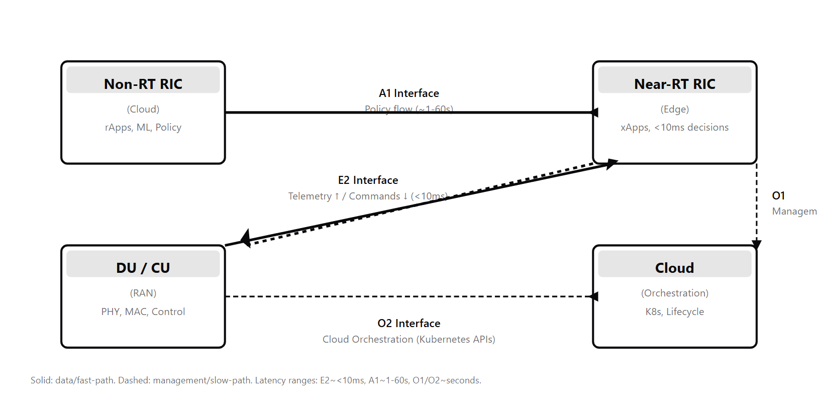
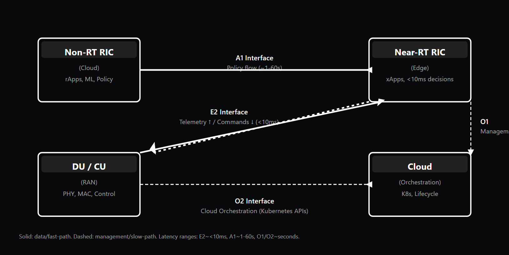
O-RAN standardizes four main interfaces to ensure interoperability: A1 Interface: Connects Non-RT RIC (cloud, strategic decisions) to Near-RT RIC (edge, real-time execution). Carries policy directives, ML model parameters, and long-timescale optimization guidance. E2 Interface: Connects the RIC to RAN nodes (DU/CU; see /topics/nr-architecture-nsa-sa-cu-du). Bidirectional: RIC sends control procedures to the RAN, RAN sends telemetry (KPMs) back. This is where real-time decisions translate into RAN actions and observations flow back. O1 Interface: Management interface. Alarms, performance counters, configuration changes, software upgrades. Not real-time; handles operational tasks. O2 Interface: Cloud infrastructure interface. Resource management, compute/storage allocation, cloud-native integration. Often uses Kubernetes APIs and cloud abstractions. The key insight: A1 is policy from the cloud to edge; E2 is control and telemetry between RIC and RAN; O1 is operational management; O2 is cloud resource management.
Why interviewers ask
Engineers building O-RAN systems must understand which interface to use for different tasks (see /topics/open-ran-o-ran-interview-prep). If a candidate confuses A1 with E2, or doesn't understand the latency/scope implications of each interface, it signals a shallow understanding of O-RAN architecture. Strong candidates can explain: (1) why the RIC is split into Non-RT and Near-RT (see /topics/near-rt-ric-vs-non-rt-ric), and why A1 connects them; (2) what KPMs (telemetry) flow over E2 and how that data informs RIC decisions; (3) the difference between control (fast, reactive, via E2) and policy (slow, strategic, via A1); (4) why O1/O2 are separate from the real-time control path.
Common mistakes
The most common mistake is treating A1 and E2 as similar. They are fundamentally different: A1 is policy from Non-RT to Near-RT RIC; E2 is control/telemetry between RIC and RAN. Another frequent gap: not understanding that E2 is bidirectional — RAN sends telemetry that the RIC reads to make decisions. Other pitfalls: assuming all four interfaces are real-time (only E2 within the RIC is <10ms), not grasping that A1 policy updates have convergence time, and missing the fact that O1/O2 are decoupled from the RAN control loop.
O-RAN Interfaces — Scope, Latency, and Data Type
| Interface | Direction | Latency Budget | Data Type | Typical Frequency | Use Case |
|---|---|---|---|---|---|
| A1 | Non-RT RIC → Near-RT RIC | Seconds to minutes | Policy, ML model params, control directives | Minutes to hours | Strategic optimization, policy updates, model distribution |
| E2 | RIC ↔ RAN (bidirectional) | < 10ms (control), ~100ms (telemetry) | KPMs (telemetry), E2AP control procedures | Milliseconds (control), seconds (KPMs) | Real-time RAN control, beam steering, power scaling, telemetry collection |
| O1 | Operator → RAN management | Minutes to hours | Alarms, counters, config, software upgrades, logs | Minutes to hours | Operational management, performance monitoring, lifecycle management |
| O2 | O-RAN system ↔ Cloud infra | Seconds | Kubernetes APIs, service lifecycle, resource allocation | Seconds to minutes | Cloud orchestration, DU/CU deployment, resource scaling, failover |
Sample interview questions
- In the O-RAN architecture, when should an operator use the A1 interface versus the E2 interface for a control decision?
- A. A1 and E2 are synonymous; they carry the same information
- B. A1 (Non-RT RIC → Near-RT RIC) is used for strategic, slow decisions (minutes to hours): ML models, policy updates, resource allocation strategies. E2 (RIC → RAN) is used for real-time, reactive decisions (<10ms): beam steering, power control, interference mitigation. Use A1 when you can wait; use E2 for immediate RAN control ✓
- C. Always use E2; A1 is redundant
- D. Use A1 only for management tasks; E2 only for data plane
Option B correctly captures the two-tier decision model. A1 and E2 operate on different timescales and are asymmetric in direction. A1 is the policy layer: the Non-RT RIC (cloud, slow, intelligent) trains an ML model or computes an optimization policy, then sends it down the A1 pipe to the Near-RT RIC (edge, fast, reactive). Example: the Non-RT RIC detects a traffic trend ("traffic spikes at 3 PM on weekdays") and sends a policy: "from 2:45-3:15 PM, reduce TX power by 10% to prevent interference." Convergence time is seconds, but the policy is high-level and strategic. E2 is the real-time control loop: the Near-RT RIC (xApps) subscribes to RAN telemetry (E2 uplink: KPMs), computes a fast decision (within ~5ms), and sends a control directive back (E2 downlink: beam angle, power value). This feedback loop runs every ~10 milliseconds. The key: A1 sets constraints or policies; E2 executes within those constraints in real-time. You cannot use E2 for everything because RAN control cannot wait seconds for a cloud RIC to compute. You cannot use A1 for everything because beam steering decisions must be nanosecond-aware, not hour-aware. Option A ignores the speed difference. Option C underutilizes A1's strategic advantage. Option D confuses planes: both A1 and E2 are control plane.
- An xApp in the Near-RT RIC needs real-time information about cell load (PRB usage) to adjust power allocation. Over which interface does it receive this telemetry, and how frequently?
- A. Over A1, every second
- B. Over O1, every minute
- C. Over E2, typically every 100-500ms via KPM subscriptions. The xApp subscribes to "PRB utilization," and the RAN reports it back at the requested interval ✓
- D. Over O2, via Kubernetes metrics
Option C is correct. The E2 interface carries telemetry (KPMs) from RAN to RIC. The xApp actively subscribes to metrics it needs, and the RAN periodically reports them. Example subscription: xApp sends an E2 subscription message: "Subscribe to PRB utilization, report every 200ms." The DU/CU then measures PRB usage every 200ms and sends back an E2 indication (uplink message) with the measured value. This feedback loop runs continuously. Frequency depends on the xApp needs: a power-control xApp might request 100-500ms updates (fast enough to react to load changes, slow enough to avoid flooding the network with telemetry). A load-balancing rApp would request 10-60 second aggregations (trends matter more than instantaneous values). A1 carries policies, not telemetry. O1 carries management data (alarms, configuration), not real-time metrics. O2 is for cloud infrastructure integration, not RAN metrics. E2 is the exclusive path for RAN telemetry. Option A, B, D are all wrong interfaces.
- The Non-RT RIC trains a new ML model for traffic prediction and wants to deploy it to all Near-RT RIC instances in a multi-region deployment. Over which interface does it send the model, and what are the synchronization challenges?
- A. Over E2 directly to the RAN
- B. Over O1 management interface
- C. Over A1 to the Near-RT RIC instances. Challenge: the model is large (multiple MB), A1 transport latency is variable, and different regions may receive the model at different times. Solution: version the model, use canary rollout (test on one region first), and allow per-region fallback to the previous model if performance degrades ✓
- D. Over O2 via cloud Kubernetes CRDs
Option C correctly identifies A1 as the policy/model distribution interface. Distributing ML models to edge instances is exactly what A1 is for. A1 advantages: it is designed for Non-RT → Near-RT communication, and it can carry structured data (serialized model weights, metadata). A1 latency is relaxed (seconds to minutes acceptable), which matches the urgency of model deployment (urgent but not millisecond-critical). Synchronization challenges are real: 1. **Model size:** A re-trained model might be 5-50 MB (depending on architecture). A1 must break this into chunks or use reliable file transfer. 2. **Version mismatch:** If region A receives v2.1 and region B still runs v2.0, their RAN decisions might conflict. Solution: add version tags and validation. 3. **Staggered rollout:** Canary deployment (test on 1-2 regions first, monitor for 10-30 minutes, then roll to others) is safer than broadcasting to all regions simultaneously. If the new model causes performance to drop, only a few regions are affected. 4. **Fallback:** if performance metrics drop after deployment, the Near-RT RIC should have a mechanism to revert to the previous model without waiting for the Non-RT RIC to notice and send a rollback command. E2 is wrong (it carries RAN control, not model data). O1 is wrong (management protocol, not real-time model sync). O2 is wrong (cloud orchestration layer, not RIC control plane).
- What is the fundamental difference between the O1 interface and the E2 interface in terms of timescale, data type, and operational purpose?
- A. O1 and E2 are identical
- B. O1 (management) operates on hour-to-day timescales, carries configuration/alarms/logs via Telecom Management protocols (NETCONF, YANG). E2 (control) operates on milliseconds, carries real-time RAN control commands and KPM telemetry via E2AP. O1 is "how the network is managed"; E2 is "how the RAN behaves in real-time" ✓
- C. O1 is faster than E2
- D. E2 is for management; O1 is for control
Option B precisely delineates the two interfaces based on timescale and purpose. **O1 (Management, Hour-to-Day Timescale):** - Protocols: NETCONF (configuration), YANG (data models), SNMP (monitoring) - Data types: MIB (Management Information Base) objects, configuration parameters, alarms, performance counters, system logs - Examples: upgrade DU software, modify MCS table, query historical fault logs, enable/disable a cell, adjust backhaul MTU - Latency: Not critical; O1 messages are buffered and may take seconds to minutes - Ownership: Operations team, network engineering, compliance **E2 (Real-Time Control, Millisecond Timescale):** - Protocol: E2AP (Application Protocol for E2 Interface) - Data types: RAN control procedures (request-response, subscriptions), KPM indications, control activations - Examples: subscribe to SINR KPM, send beam steering command, request RIC service model capabilities - Latency: <10ms end-to-end; timing-sensitive - Ownership: RIC applications (xApps, rApps) The separation is crucial: O1 changes the system configuration over hours; E2 reacts to radio conditions over milliseconds. Conflating them causes operational confusion (e.g., trying to update a KPM subscription via O1 will fail because O1 does not support dynamic subscriptions). Option A misses the critical distinction. Option C reverses the timescale. Option D swaps the interfaces.
- In a cloud-native O-RAN deployment, the CU is a containerized microservice running in Kubernetes. How does the O2 interface facilitate CU lifecycle management (deploy, scale, failover)?
- A. O2 does not handle lifecycle management; that is done by the RIC
- B. O2 provides APIs (often based on ETSI NFV) that allow O-RAN orchestrators to declare CU resource requests, invoke Kubernetes operations (pod creation, scaling, node affinity), and monitor pod health. When a CU pod fails, Kubernetes (coordinated via O2) reschedules it on a healthy node and updates the RAN control plane via E2 ✓
- C. O2 only monitors performance; it does not control lifecycle
- D. Kubernetes manages everything; O2 is not needed
Option B correctly describes O2's role as the bridge between RAN control plane and cloud orchestration. Traditional RAN (monolithic base stations) has no cloud orchestration—the hardware is static, bolted to a tower or data center. In cloud-native O-RAN, DU and CU are containerized, so they can move, scale, and fail over like any other Kubernetes workload. O2 enables this: 1. **Lifecycle declaration:** An operator declares "I want to deploy a 5G CU. It needs 16 vCPU, 32 GB RAM, 1 Gbps network, and persistent storage for state." This is sent via O2 API to the Kubernetes cluster. 2. **Pod orchestration:** Kubernetes receives the O2 request, creates a CU deployment with the specified resources (via a Kubernetes Deployment or StatefulSet), and schedules pods on healthy nodes. 3. **Health integration:** Kubernetes monitors pod health (CPU, memory, readiness probes). If a CU pod becomes unhealthy, Kubernetes reschedules it. O2 notifies the RAN control plane (via E2) that the CU is being migrated, so E2 connections are updated. 4. **Storage state:** If CU state (UE context, RRC state, SLA data) must survive pod migration, O2 allocates PersistentVolumes. The new CU pod mounts the same PV and continues where the old pod left off. Without O2, the RAN control plane would not know about Kubernetes operations, causing E2 messages to reach dead CU pods and UE state to be lost during failover. Option A is wrong: O2 is explicitly for lifecycle. Option C underestimates O2's role. Option D ignores that O-RAN needs a control-plane-aware orchestration layer.
- An xApp running in the Near-RT RIC needs to adjust interference mitigation by sending a new power limit to multiple DUs. Which interfaces would this operation touch, in what order?
- A. A1 → E2
- B. E2 only (xApp queries DUs directly via E2) ✓
- C. O1 → O2
- D. This operation requires updates to the Non-RT RIC policy, which flows down A1, and then the xApp implements the policy by sending power-limit control activations via E2 downlink
I need to correct my analysis here. Option B (E2 only) is actually the most direct, but Option D describes the full flow including policy governance. For an immediate intervention by an xApp (no policy change): **E2 only** — the xApp sends a control activation message (E2 downlink) directly to the DU saying "set TX power to -10 dBm." This bypasses A1 entirely because the decision is tactical (immediate), not strategic (policy-governed). For a sustained strategy (e.g., "interference is chronically high in this region; reduce power by 10% starting at 3 PM"): **A1 → E2** — the Non-RT RIC sends a policy via A1 to the Near-RT RIC: "apply power reduction policy X from 3-5 PM." The Near-RT RIC xApp then uses this policy as a constraint in its E2 control activations. When 3 PM arrives, the xApp's E2 downlink messages include the power reduction. O1 and O2 are not involved in real-time control, so options A and C are wrong. The most likely interview answer is: **E2 for immediate actions; A1 → E2 for policy-driven sustained actions.** If the question specifies "just adjust" (immediate), answer E2. If it says "establish a policy," answer A1 → E2.
- Compare the data flow for E2AP (Asn.1-based messages) versus A1 message serialization. Why might they differ?
- A. E2AP and A1 use identical serialization; the difference is only the source/destination
- B. E2AP uses Asn.1 (compact, type-safe, standardized by 3GPP). A1 is less rigidly specified and may use JSON, protobuf, or other formats depending on vendor implementation. E2 prioritizes latency/bandwidth efficiency (millisecond-scale); A1 prioritizes flexibility and ease of integration with cloud ecosystems ✓
- C. A1 is faster because it uses Asn.1; E2 is slower
- D. Serialization format has no impact on performance
Option B is correct. The choice of serialization reflects the different design goals of the two interfaces. **E2AP (Asn.1):** - Compact binary encoding: every bit counts when messages run every ~10ms - Type-safe: Asn.1 schema enforces strict data types, reducing parsing errors - Standardized by 3GPP: aligned with existing RAN protocols (NR, LTE) - Deterministic size: E2 control messages have predictable size, aiding scheduling - Example: a beam-steering command might be 50-100 bytes in Asn.1 **A1 (flexible):** - Many vendors use JSON or protobuf (cloud-native favorites) - Loose schema: policies can be extended without major protocol upgrades - Human-readable (JSON): operations teams can inspect and debug policies - Size is less critical: A1 messages are infrequent (seconds), not milliseconds - Example: an ML model policy might be JSON with metadata, readable for auditing The philosophical difference: E2 is real-time hardware-class communication (like 5G PHY layer); A1 is cloud middleware (like REST APIs). Different speed regimes demand different tradeoffs. Option A ignores the design rationale. Option C is backwards. Option D is wrong: serialization has huge impact on latency and bandwidth.
- If an O-RAN system loses connectivity on the E2 interface (RIC ↔ RAN) for 5 minutes, what is the expected behavior?
- A. The RAN continues to operate normally; E2 is not essential
- B. The RAN falls back to pre-configured default policies and static configurations (no RIC control). RIC-dependent features (xApps, dynamic resource allocation) are suspended. When E2 connectivity is restored, the RIC resyncs with the RAN. This is called E2 "heartbeat failure recovery" and is essential for system resilience ✓
- C. The RAN stops operating entirely
- D. The RAN switches to non-RT RIC control via A1
Option B describes the correct graceful degradation. E2 outages are expected in operational networks (maintenance, link failures), so systems must handle them. **What happens during E2 outage:** 1. The Near-RT RIC detects E2 messages are not being acknowledged (no KPM indications returned, control activations go unconfirmed). 2. After a timeout (~5-10 seconds), the RIC declares E2 down and stops sending control activations. 3. The DU/CU reverts to default behavior: static power settings, no dynamic beam steering, basic scheduler (round-robin instead of RIC-optimized). QoS may degrade, but the RAN stays up. 4. The RAN continues to operate on these defaults for the duration of the outage. 5. When E2 is restored (heartbeat message or ping succeeds), the RIC and RAN re-establish synchronization. The RIC sends "I'm back, acknowledge with your current state" messages; the RAN responds with pending metrics; the RIC resyncs xApps and resumes control. This design treats E2 as a distributed system with partition tolerance: the RAN can survive RIC disconnection, and the RIC can eventually recover. Option A underestimates E2's role: without RIC control, the RAN cannot adapt to changing conditions (e.g., interference, mobility). Option C is too pessimistic: a well-designed RAN doesn't crash. Option D confuses tiers: A1 requires E2 connectivity to be meaningful (A1 policies guide Near-RT, which controls via E2).
Frequently asked questions
- What is the A1 interface?
- The A1 interface connects the Non-RT RIC (cloud) to the Near-RT RIC (edge). It carries policy decisions, ML model updates, and control directives that guide Near-RT decisions. A1 is how strategic, cloud-based decisions steer real-time, edge-based actions.
- What is the E2 interface?
- The E2 interface connects the RIC (Near-RT and Non-RT) to the RAN nodes (DU/CU). It is bidirectional: the RIC sends control/activation to the RAN (via E2AP procedures), and the RAN sends telemetry (KPMs — Key Performance Measurements) back to the RIC for monitoring and decision-making.
- What is the O1 interface?
- The O1 interface is the management interface. It carries operational, administrative, and maintenance data: alarms, counters, config changes, software upgrades. O1 is not real-time; it handles long-timescale management tasks.
- What is the O2 interface?
- The O2 interface connects the O-RAN systems to the cloud infrastructure layer (compute, storage, networking). It handles service management, resource allocation, and cloud-RAN integration — often using cloud-native APIs.
- How do you choose between A1 and E2 for a control decision?
- If the decision can wait (milliseconds to seconds), and benefits from cloud intelligence (ML, policy, long-term optimization), use A1: Non-RT RIC trains a model, sends it down via A1 to the Near-RT RIC. If the decision is fast-path (sub-10ms, reactive), it stays in the Near-RT RIC and may use E2 to query RAN state or activate control.
- What are typical A1 policy examples in O-RAN?
- A1 policies steer Near-RT RIC behavior over longer timescales. Examples: (1) Interference mitigation policy — reduce power in congested cells during peak hours; (2) Load-balancing policy — shift traffic from overloaded to underutilized cells; (3) ML model updates — send a re-trained beam-prediction model every 10 minutes; (4) Resource allocation strategy — prioritize latency-sensitive slices during business hours. Each policy is sent from Non-RT RIC to Near-RT RIC via A1 and takes effect within seconds.
- How do KPMs flow over E2, and what types are measured?
- KPMs (Key Performance Measurements) are metrics exported by RAN nodes (DU/CU) over the E2 interface to the RIC. Types include: (1) Radio metrics — SINR, CQI, throughput per UE; (2) Resource utilization — PRB usage, power consumption, queue depths; (3) Reliability — handover success rate, HARQ retransmission rate; (4) Latency — DL/UL packet delay. Both Near-RT xApps (for immediate reaction) and Non-RT rApps (for trend analysis) consume these KPMs. The RIC can filter or subscribe to specific KPMs to reduce overhead.
- How is O1 management (TMO) different from real-time control?
- O1 (via Telecom Management protocols like NETCONF, YANG) manages the long-timescale aspects: configuration, alarms, performance counters, software lifecycle. Unlike E2 (which is millisecond real-time) or A1 (which is second-scale policy), O1 operates on hour-to-day timescales. Example: a DU's software upgrade happens via O1, not E2. An operator uses O1 APIs to query historical alarms, adjust MIB (Management Information Base) parameters, or fetch daily traffic reports. O1 is essential for operations but separate from the RAN control loop.
- How do O2 Kubernetes APIs integrate DU/CU lifecycle in O-RAN?
- O2 connects O-RAN systems to cloud orchestration (typically Kubernetes via ETSI NFV). In a cloud-native O-RAN deployment, DU and CU are containerized microservices. O2 APIs handle: (1) Service lifecycle — deploy/scale/delete DU/CU containers using Kubernetes namespaces and CRDs; (2) Resource requests — declare CPU, memory, network requirements; (3) Health monitoring — pod readiness, resource constraints, failover orchestration; (4) Storage management — PVC (PersistentVolumeClaim) for state. O2 is the integration point between the RAN's E2/A1 control plane and the cloud's container orchestration, ensuring DU/CU survive node failures via Kubernetes rescheduling.
Related topics
Essential AI-Native Skills for O-RAN Interfaces Explained: A1, E2, O1, and O2
Modern engineering work increasingly uses AI tools for design and code review, debugging, documentation, test and testbench generation, and workflow automation. The goal is not to let AI replace engineering judgment — it is to move faster while keeping verification discipline.
- Use AI to explain unfamiliar code, logs, waveforms, datasheets, or test failures.
- Break large problems into small, reviewable steps you can verify independently.
- Ask AI for hypotheses, then validate them against tests, measurements, simulations, or lab data.
- Version-control your analysis scripts, testbenches, and configs — keep changes small and reviewable.
- Document your assumptions, design tradeoffs, and debugging decisions.
- Verify AI output before trusting it: run the checks that fit the domain — unit tests, linters, simulations, or bench/lab measurements.
- Review AI output for correctness, edge cases, and real-world consequences.
O-RAN Interfaces Explained: A1, E2, O1, and O2 — coming to the question bank
The adaptive practice engine is already live for core wireless, RF, and ML systems. O-RAN Interfaces Explained: A1, E2, O1, and O2 isn't covered in the question bank yet — get notified when it's added.