NR Beam Management: SSB Sweep, P-1/P-2/P-3, TCI States, QCL Interview Prep
5G NR beam management — SSB beam sweep, P-1/P-2/P-3 refinement, TCI states and activation, QCL types, and beam failure recovery.
Quick answer
NR beam management is the foundational layer for FR2 (mmWave) deployments and a meaningful supporting layer for FR1 deployments with large arrays.
Beam management is the most operationally important 5G modem topic for FR2 deployments and one of the most-asked architectural topics for FR1 deployments with massive MIMO.
Editorial review
Written by
CompoundLearn editorial team
Wireless / RF / hardware engineering
Reviewed by
CompoundLearn editorial team
Wireless / RF / hardware engineering
Last reviewed
Built from curated topic maps, editorial validation, and subject-matter review so the page stays aligned with the interview intent and the current content pipeline.
What it is
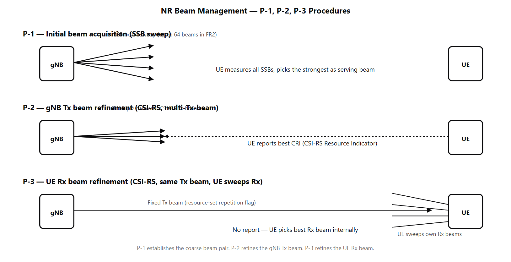
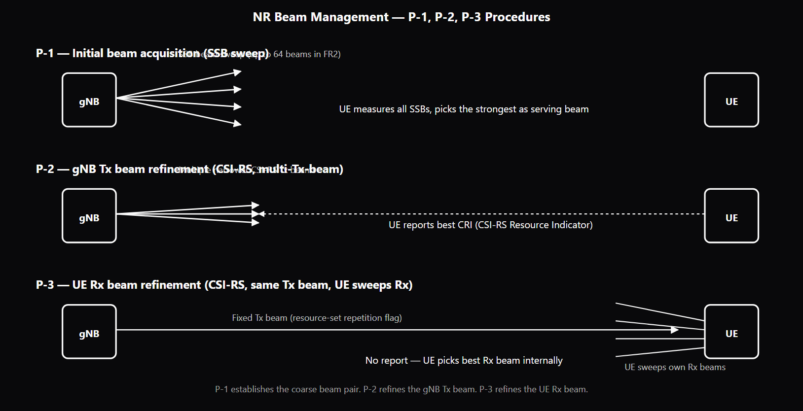
NR beam management is the foundational layer for FR2 (mmWave) deployments and a meaningful supporting layer for FR1 deployments with large arrays. At FR2 the gNB and UE use narrow analog beams that require continuous selection, refinement, and recovery as channel conditions and UE position change. Without the right beam pair, the UE simply does not see the cell — beam management is therefore both the access-layer enabler and the operational-quality determinant for FR2. The NR architecture organizes beam management into procedures. P-1 is initial beam acquisition: during each SS burst set the gNB transmits multiple SSB instances, each on a different beam direction; the UE measures all of them and picks the strongest as the serving beam. The maximum number of SSB beams varies with frequency range (up to 4 in low FR1, 8 in mid-FR1, 64 in FR2). The SSB index the UE picked feeds the RACH procedure via SSB-to-RACH-occasion mapping so the gNB knows which beam direction the UE is in (see /topics/nr-initial-access-ssb-rach). P-2 is gNB-side beam refinement. The gNB configures a CSI-RS resource set (see /topics/nr-reference-signals) with multiple narrower beams within the wider P-1 beam direction. The UE measures all and reports the best CRI (CSI-RS Resource Indicator). The result is a tighter gNB Tx beam with higher beamforming gain. P-3 is UE-side beam refinement. The gNB configures a CSI-RS resource set with all resources on the same Tx beam (repetition flag set so the UE knows the Tx beam is fixed); the UE sweeps its own Rx beams across the resources and identifies the best, internal to the UE. P-1 establishes the coarse beam pair, P-2 refines the gNB side, P-3 refines the UE side. TCI states are the abstraction NR uses to tell the UE which RS source to use as the channel and beam reference for each scheduled transmission. A TCI state binds a downlink channel (PDCCH or PDSCH — see /topics/nr-physical-channels) to one or two source RS (CSI-RS, SSB) plus a QCL type. The three-layer activation (RRC configures the pool, MAC CE activates a subset (see /topics/nr-mac-scheduling), DCI selects one per transmission) lets the network update beam associations at multiple timescales without RRC reconfiguration cost. QCL (Quasi-Co-Location) defines what channel properties two RS share. Type-A covers the large-scale time-and-frequency parameters (Doppler shift, Doppler spread, average delay, delay spread). Type-D covers the spatial-RX parameters — the receive-beam configuration the UE used when measuring the source RS. At FR2, Type-D is critical: without it the UE does not know which Rx beam to point during the scheduled transmission. TCI-state configuration typically pairs Type-A (time/freq tracking source) with Type-D (Rx-beam hint). Beam-failure detection and recovery handle the operational lifecycle. BFD counts consecutive Beam Failure Instances (BFI) — declared when the BLER on the configured beam-failure-detection RS exceeds a threshold — and triggers BFR when the count crosses the configured maximum. BFR issues a BFR Request on either a dedicated PUCCH resource or a contention-free PRACH preamble, depending on configuration, and recovers in tens of ms rather than falling back to RRC re-establishment.
Why interviewers ask
Beam management is the most operationally important 5G modem topic for FR2 deployments and one of the most-asked architectural topics for FR1 deployments with massive MIMO. The procedure split (P-1, P-2, P-3) and the TCI/QCL framework reveal whether a candidate has worked at the FR2 deployment layer or only studied the architecture textbook. The QCL Type-D question is the most diagnostic single question. Strong candidates can describe what Type-D conveys (spatial-RX parameters, i.e., the Rx-beam configuration), why it matters at FR2 (narrow Rx beams), and the typical pairing in a TCI state (Type-A for time/freq tracking, Type-D for Rx-beam hint). Weak candidates can name the QCL types but cannot describe what each covers or when each is used. The TCI-state activation chain (RRC → MAC CE → DCI) is probed because it is the deliberate three-timescale design. Candidates who describe TCI states as RRC-only configuration miss the per-transmission DCI selection that makes the framework operationally efficient. Strong candidates explain that the MAC CE activation lets the network update the active set quickly without an RRC reconfiguration, and the DCI selection makes the per-PDSCH beam association near-zero-overhead. The BFR design is probed because it is the FR2 deployment-quality lever. Candidates who describe beam failure as triggering RRC re-establishment or handover miss the BFR procedure entirely; BFR exists specifically because RRC-level recovery would be too slow for the transient blockages typical at FR2 (body shadowing, hand blockage, walking around a corner). The PUCCH-versus-PRACH BFR fallback chain reveals whether the candidate has worked at the BFR-debug level. P-1/P-2/P-3 separation is probed because the architectural rationale is non-obvious. Strong candidates explain why three procedures exist — coarse acquisition (P-1), gNB-side refinement (P-2), UE-side refinement (P-3) — and which RS each uses. Weak candidates collapse the three into "beam management" without naming them, missing the FR2 deployment-tuning surface.
Common mistakes
The most common mistake is collapsing beam management into "the network picks a beam" without naming the procedures or the RS that each uses. P-1 uses SSB sweep, P-2 uses CSI-RS with multiple Tx beams, P-3 uses CSI-RS with the same Tx beam and the repetition flag set. Candidates who treat these as interchangeable miss the architectural split. A second gap is misunderstanding QCL Type-D. Some candidates think Type-D refers to Doppler (it does not — Doppler is in Type-A, B, C). Some think Type-D applies to uplink (it applies to downlink Rx beam at the UE). Some collapse all QCL types into one. Strong candidates know Type-D specifically covers the UE-side Rx-beam configuration and that it is the FR2 architectural addition. A third gap is missing the TCI activation chain. RRC-configured pool is too large for direct DCI selection; MAC CE activation reduces the pool to the active set; DCI picks one per transmission. Candidates who describe TCI as "RRC only" or "DCI only" miss the deliberate three-layer design. A fourth gap is treating beam failure as a mobility event. Beam failure detection counts BFIs against a threshold, beam failure declaration triggers BFR (not handover), and BFR completes in tens of ms via PUCCH or contention-free PRACH. Candidates who describe beam failure as triggering handover or RRC re-establishment have not worked at the FR2 deployment layer where BFR is the routine recovery mechanism. A fifth gap is missing the wide-beam vs refined-beam trade-off. Wide beams are robust to mobility and have lower beamforming gain; refined beams have higher gain but require the UE to stay aligned long enough for the refinement to remain valid. Operators tune this per UE based on mobility and link conditions; candidates who do not surface this trade-off miss the operational lever. See /topics/mimo for the broader MIMO context and /topics/beamforming for the digital/hybrid/analog beamforming architecture options that underlie NR's beam management framework.
QCL Types A–D — Channel Properties Shared
| QCL Type | Doppler Shift | Doppler Spread | Average Delay | Delay Spread | Spatial RX | Typical Pairing |
|---|---|---|---|---|---|---|
| Type-A | ✓ | ✓ | ✓ | ✓ | ✗ | TRS → PDSCH-DMRS (time/freq tracking source) |
| Type-B | ✓ | ✓ | ✗ | ✗ | ✗ | Used less often; partial inheritance for special cases |
| Type-C | ✓ | ✗ | ✓ | ✗ | ✗ | SSB → CSI-RS (initial association) |
| Type-D | ✗ | ✗ | ✗ | ✗ | ✓ | CSI-RS or SSB → PDSCH/PDCCH (FR2 receive-beam hint) |
Sample interview questions
- A UE receives a TCI-state activation for PDSCH that references CSI-RS Resource A as the source RS with QCL Type-D. What spatial reception assumption does the UE apply, and why is QCL Type-D specifically called out?
- A. The UE assumes Resource A and the PDSCH share Doppler shift only — Type-D refers to Doppler.
- B. QCL Type-D tells the UE the PDSCH and CSI-RS Resource A share the same spatial-RX parameters — that is, the UE should use the same receive beam (or panel/array configuration) it used when measuring Resource A. Type-D is the only QCL type that addresses spatial reception, which is the dominant concern at FR2 where the UE has narrow analog receive beams. ✓
- C. QCL Type-D applies only to uplink transmissions, not PDSCH reception.
- D. QCL Type-D is identical to QCL Type-A; the letter is just for backward compatibility.
Option B is correct. QCL (Quasi-Co-Location) defines which channel properties two reference signals share. Type-A covers Doppler shift, Doppler spread, average delay, and delay spread. Type-B covers Doppler shift and Doppler spread. Type-C covers Doppler shift and average delay. Type-D is unique — it covers spatial-RX parameters, which is the receive-beam configuration the UE used to measure the source RS. Type-D matters at FR2 because the UE has narrow analog receive beams. When the gNB tells the UE "PDSCH is QCL Type-D with CSI-RS Resource A," it is saying "use the same receive beam you used when you measured Resource A." Without this hint, the UE would not know which of its candidate receive beams to point during PDSCH demodulation, and at FR2 the wrong beam means no signal at all. Option A confuses Type-D with Type-B/C. Option C is wrong — Type-D applies to PDSCH reception (where the UE's receive beam matters), not uplink. Option D collapses architecturally different QCL types. Production reality: TCI-state configuration with Type-D is one of the most operationally important parts of FR2 deployments; misconfiguration results in UE-side beam-mismatch and dropped PDSCH decode without a clear root cause.
- A UE in RRC_CONNECTED detects N consecutive beam-failure instances (BFI). What procedure does the UE trigger, and what is the difference between BFR via PUCCH versus BFR via PRACH?
- A. The UE immediately performs full RRC re-establishment.
- B. The UE issues a measurement report and waits for the network to trigger handover.
- C. The UE triggers Beam Failure Recovery (BFR). If a dedicated PUCCH BFR resource is configured and the UE has identified a new candidate beam with sufficient RSRP, it sends a BFR Request on PUCCH (faster, contention-free). If no PUCCH BFR resource is configured or the UE has lost all beams, it falls back to a contention-free PRACH BFR procedure using a dedicated preamble assigned for BFR — still much faster than full re-establishment because the UE skips the contention round and the network-side RRC state is preserved. ✓
- D. BFR via PUCCH and BFR via PRACH are identical — only the link used differs.
Option C is correct. NR Beam Failure Recovery (BFR) is the procedure that lets a UE quickly recover from beam loss without falling back to full RRC re-establishment. Beam Failure Detection (BFD) counts consecutive BFIs (Beam Failure Instances) — each BFI is declared when the BLER on the configured beam-failure-detection RS exceeds a threshold for a measurement period. When the BFI count reaches the configured beamFailureInstanceMaxCount, beam failure is declared and BFR is triggered. BFR via PUCCH: configured dedicated PUCCH resource that the UE uses to send a single-bit BFR Request indicating it has identified a new candidate beam. The DCI from the gNB then schedules a PDSCH/PUCCH exchange to confirm the new beam and complete BFR. Fast, contention-free, but requires the UE to find a viable candidate beam first. BFR via PRACH: contention-free RACH on a dedicated preamble pre-assigned for BFR. Used when the UE has no PUCCH BFR resource or has lost the active serving beam without yet identifying a candidate. The contention-free PRACH bypasses the MSG3/MSG4 contention-resolution round, so it is much faster than ordinary RACH. Option A reaches for re-establishment, which is the absolute fallback if BFR also fails — far too pessimistic for a typical beam failure. Option B describes mobility, not BFR. Option D collapses architectural differences. Production reality: at FR2 the UE may experience transient beam failures from hand blockage, body shadowing, or rapid mobility; BFR is designed specifically to make these recoverable in tens of ms rather than triggering a handover or re-establishment.
- How does the P-1 / P-2 / P-3 beam-management procedure family differ in purpose, and which RS does each use?
- A. P-1, P-2, P-3 are all UE-side procedures using only DMRS.
- B. P-1, P-2, P-3 are all gNB-side procedures using only PDCCH measurements.
- C. P-1, P-2, P-3 are interchangeable names for the same procedure.
- D. P-1 is initial beam acquisition using SSB sweep — the gNB sweeps multiple SSB beams and the UE picks the strongest. P-2 is gNB-side beam refinement using CSI-RS — the gNB transmits multiple narrow CSI-RS beams within the wider P-1 beam and the UE reports the best. P-3 is UE-side beam refinement using a CSI-RS resource set with the same Tx beam — the UE sweeps its own receive beams while the gNB transmits, picking the best UE-side beam. P-1 establishes the beam pair; P-2 refines the gNB Tx beam; P-3 refines the UE Rx beam. ✓
Option D is correct. The three-procedure split exists because FR2 beam management has three distinct refinement targets: which gNB Tx beam to use, refining the gNB Tx beam to a narrower beam within the wider acquisition beam, and refining which UE Rx beam to use against a fixed gNB Tx beam. P-1 uses SSB sweep for initial beam acquisition. The gNB transmits an SS burst set with multiple SSB beams (each on its own SSB index), the UE measures each, and the UE picks the strongest as the serving beam. This establishes the initial coarse beam pair and feeds into the RACH procedure via SSB-index-to-RACH-occasion mapping (see /topics/nr-initial-access-ssb-rach). P-2 uses CSI-RS resource sets configured with multiple resources, each transmitted by a different (narrower) gNB Tx beam within the wider P-1 beam. The UE measures all and reports the best CRI (CSI-RS Resource Indicator). This refines the gNB Tx beam to a tighter, higher-gain beam. P-3 uses a CSI-RS resource set configured with all resources on the same gNB Tx beam but the resource-set repetition flag enabled. The UE knows the same Tx beam is used, so it sweeps its own Rx beams (one per CSI-RS resource) and identifies the best Rx beam. The UE does not need to report — the result is internal to the UE. Option A misses that beam management uses SSB and CSI-RS, not DMRS. Option B inverts the roles — P-1 and P-2 are network-driven, P-3 is UE-internal. Option C collapses real procedural distinctions. Production reality: FR2 deployments require all three to operate; without P-3 the UE cannot refine its own receive beam against the fixed gNB beam, leaving a meaningful chunk of beamforming gain on the table.
Frequently asked questions
- What is NR beam management?
- NR beam management is the set of procedures that establishes, refines, monitors, and recovers the beam pair between a gNB and a UE. At FR1 (sub-6 GHz) beamforming is usually digital with relatively wide beams, and explicit beam management is less critical. At FR2 (24+ GHz) beams are narrow, analog beamforming is dominant, and beam management is the foundation that everything else rests on — without the right beam pair, the UE simply does not see the cell. NR organizes beam management into procedures: P-1 (initial beam acquisition via SSB sweep), P-2 (gNB Tx beam refinement via CSI-RS), P-3 (UE Rx beam refinement via CSI-RS), plus beam-failure detection (BFD) and beam-failure recovery (BFR) for the operational lifecycle.
- What is the SSB beam sweep?
- During an SS burst set period (default 20 ms), the gNB transmits multiple SSB instances, each on its own SSB index, each carried on a different beam direction. The UE detects all SSBs it can decode and ranks them by RSRP, picking the strongest as its serving beam during cell acquisition. The maximum number of SSB beams varies by frequency range: up to 4 in FR1 sub-3 GHz, up to 8 in FR1 3–6 GHz, up to 64 in FR2. The SSB beam sweep is the P-1 procedure and is the foundation of initial beam acquisition. The SSB index the UE picked also feeds into the RACH procedure via SSB-to-RACH-occasion mapping so the gNB knows which beam direction the UE is in (see /topics/nr-initial-access-ssb-rach).
- What are the P-1, P-2, and P-3 procedures?
- P-1 is initial beam acquisition using SSB sweep — the gNB sweeps multiple SSB beams during the SS burst set, the UE measures all of them, and the UE picks the strongest as the serving beam. P-2 is gNB Tx beam refinement using a CSI-RS resource set configured with multiple narrower beams; the UE measures all and reports the best via a CRI report. P-3 is UE Rx beam refinement using a CSI-RS resource set where the gNB transmits the same Tx beam on all resources (resource-set repetition flag set); the UE knows the Tx beam is fixed and sweeps its own Rx beams to identify the best, internal to the UE without a report. P-1 establishes the coarse beam pair, P-2 refines the gNB side, P-3 refines the UE side.
- What are TCI states?
- TCI (Transmission Configuration Indicator) state is the abstraction NR uses to tell the UE which reference signal source to associate with which scheduled transmission. A TCI state binds a downlink channel (PDCCH or PDSCH) to one or two source RS (CSI-RS, SSB) and a QCL type. The UE uses the source RS measurement as its channel-estimation and beam reference for the bound channel. TCI states are configured via RRC (a pool of up to 128 TCI states per BWP), then activated by MAC CE (a subset becomes the active pool). For PDSCH, the DCI TCI field then selects one state per scheduled transmission from that active pool; the TCI for a PDCCH/CORESET is instead indicated by MAC CE, not chosen per-transmission by DCI. This layered activation (RRC → MAC CE → DCI for PDSCH) lets the network update beam associations at multiple timescales without RRC-level reconfiguration cost.
- What are QCL (Quasi-Co-Location) types?
- QCL defines which channel properties two reference signals share. Type-A covers Doppler shift, Doppler spread, average delay, and delay spread — the "large-scale parameters" that determine how the receiver tunes its time and frequency tracking. Type-B covers only Doppler shift and Doppler spread. Type-C covers only Doppler shift and average delay. Type-D covers spatial-RX parameters — the receive-beam configuration. Type-D is the FR2-critical type because at high frequency the UE's narrow Rx beam matters; without Type-D the UE does not know which Rx beam to point during the scheduled transmission. TCI-state configuration typically includes one Type-A entry plus one Type-D entry: the Type-A tells the UE how to set its time/frequency tracking, the Type-D tells the UE which Rx beam to use.
- What is beam-failure detection (BFD)?
- BFD is the procedure by which a UE in RRC_CONNECTED detects that its active beam has failed. The UE monitors a configured beam-failure-detection reference signal (typically a CSI-RS resource or an SSB) and measures the hypothetical BLER assuming a transmission on that beam. When the BLER exceeds a configured threshold for a measurement period, a Beam Failure Instance (BFI) is declared. When the count of consecutive BFIs reaches the configured beamFailureInstanceMaxCount, a beam failure is declared and BFR is triggered. The mechanism is tuned to distinguish transient blockage (a single BFI cleared by improving channel conditions) from persistent beam loss (BFI count crosses the threshold).
- What is beam-failure recovery (BFR)?
- BFR is the recovery procedure triggered when beam failure is declared. The UE identifies a new candidate beam by measuring the configured candidate-beam RS set (a configured pool of SSB and/or CSI-RS resources, each with an RSRP threshold). If at least one candidate has sufficient RSRP, the UE issues a BFR Request — either on a dedicated PUCCH resource (fast, configured for BFR) or on a contention-free PRACH preamble pre-assigned for BFR. The gNB receives the request, learns the new candidate beam, and schedules a PDCCH on the new beam to complete recovery. BFR completes in tens of ms typically, much faster than RRC re-establishment.
- When is wide-beam vs refined-beam strategy used?
- Wide-beam transmission (the broader P-1 beam from the SSB sweep) is used for initial access and during fast UE mobility where a narrow beam would lose the UE between refinement opportunities. Refined-beam transmission (a tighter P-2 or P-3 beam) gives higher beamforming gain — more SINR margin, higher MCS, longer reach — but requires the UE to stay close to the same direction long enough for the refinement to remain valid. Operators tune this per scenario: high-mobility UEs may stay on the wider beam, stationary or slow-moving UEs are pushed to the refined beam. The TCI-state activation framework lets the network switch a UE between wide-beam and refined-beam configurations without RRC reconfiguration.
Related topics
Siblings
- 5G NR Explained: Numerology, BWP, HARQ, and Frame Structure
- Beamforming Interview Guide: Analog vs Digital vs Hybrid
- MIMO Explained: Spatial Multiplexing, Rank, Massive MIMO
- NR Reference Signals: DMRS, CSI-RS, SRS, PTRS, and the SSB
- NR Initial Access: SSB, MIB, SIB1, and the RACH Procedure
- Antenna Design
- 5G NR Handover: Xn vs N2, Conditional HO, Beam Failure Recovery
- PDCCH, PDSCH, PUCCH, PUSCH: The 5G NR Physical Channels
Practice
Essential AI-Native Skills for NR Beam Management: SSB Sweep, P-1/P-2/P-3, TCI States, QCL
Modern engineering work increasingly uses AI tools for design and code review, debugging, documentation, test and testbench generation, and workflow automation. The goal is not to let AI replace engineering judgment — it is to move faster while keeping verification discipline.
- Use AI to explain unfamiliar code, logs, waveforms, datasheets, or test failures.
- Break large problems into small, reviewable steps you can verify independently.
- Ask AI for hypotheses, then validate them against tests, measurements, simulations, or lab data.
- Version-control your analysis scripts, testbenches, and configs — keep changes small and reviewable.
- Document your assumptions, design tradeoffs, and debugging decisions.
- Verify AI output before trusting it: run the checks that fit the domain — unit tests, linters, simulations, or bench/lab measurements.
- Review AI output for correctness, edge cases, and real-world consequences.
NR Beam Management: SSB Sweep, P-1/P-2/P-3, TCI States, QCL — coming to the question bank
The adaptive practice engine is already live for core wireless, RF, and ML systems. NR Beam Management: SSB Sweep, P-1/P-2/P-3, TCI States, QCL isn't covered in the question bank yet — get notified when it's added.