Beamforming Interview Guide: Analog vs Digital vs Hybrid Interview Prep
Beamforming for wireless & RF interviews — analog vs digital vs hybrid, codebook vs reciprocity precoding, and the mmWave trade-offs interviewers probe.
Quick answer
Beamforming is the use of phased antenna arrays (see /topics/antenna-design) to focus radio energy toward chosen directions and away from others — the technology behind 5G NR mmWave coverage, Wi-Fi 6/7/8 (802.11ax/be/bn) multi-user transmission, and modern radar.
Beamforming questions test whether a candidate can hold antenna theory, signal processing, and system design in one head simultaneously.
Editorial review
Written by
CompoundLearn editorial team
Wireless / RF / hardware engineering
Reviewed by
CompoundLearn editorial team
Wireless / RF / hardware engineering
Last reviewed
Built from curated topic maps, editorial validation, and subject-matter review so the page stays aligned with the interview intent and the current content pipeline.
What it is
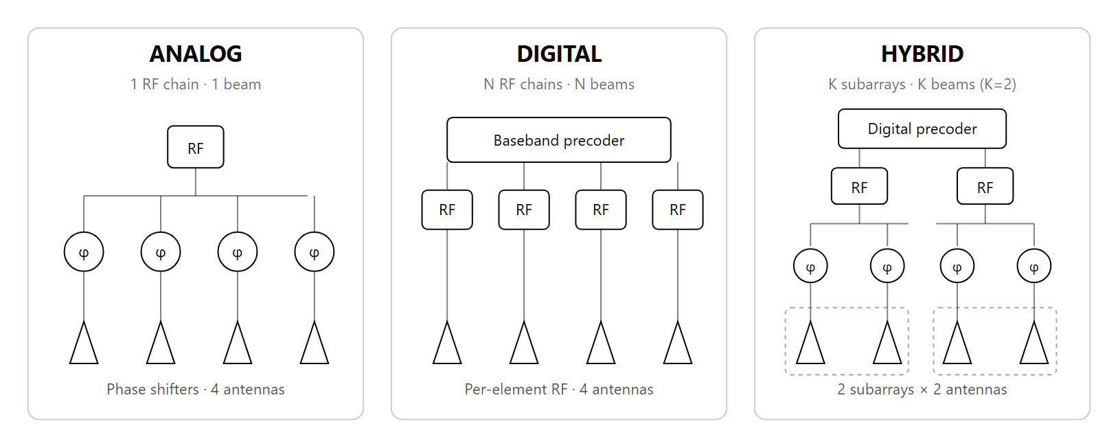
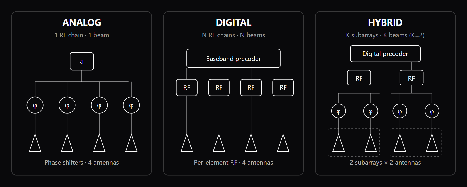
Beamforming is the use of phased antenna arrays (see /topics/antenna-design) to focus radio energy toward chosen directions and away from others — the technology behind 5G NR mmWave coverage, Wi-Fi 6/7/8 (802.11ax/be/bn) multi-user transmission, and modern radar. The fundamental tool is a complex weight vector applied across array elements; varying the weights steers the main lobe, controls sidelobes, and creates spatial nulls. Beamforming comes in three flavors. Analog beamforming applies the weights at RF using phase shifters and a single RF chain — cheap, power-efficient, but locked to one beam at a time. Digital beamforming gives every element its own RF chain and applies weights in baseband — fully flexible, supports many simultaneous beams and per-user MU-MIMO precoders (see /topics/mimo), but expensive in silicon and DC power. Hybrid beamforming, the workhorse of mmWave 5G, combines an analog beam selection in front of digital baseband precoding to cap RF-chain count while preserving multi-stream flexibility. Algorithms range from delay-and-sum, MVDR, and LCMV at the classical end through MMSE-based per-user precoders, eigen-beamforming via SVD of the channel matrix, and codebook-based PMI feedback in 3GPP standards. Modern systems also span 3D (azimuth + elevation) beamforming for full-dimension MIMO and grid-of-beams designs that tile the cell coverage with a fixed beam set used during SSB sweeping in 5G NR. Deployment reality forces hybrid architectures to dominate above 6 GHz: pure digital RF-chain cost — DAC, mixer, PA, LNA per element — is intractable when element counts climb to 128 or 256 in a single panel, and DC power scales linearly with chain count. Pure analog cannot serve multi-user MIMO because phase-only weights at a single RF chain cannot synthesize independent per-user beams. The right architecture is therefore an engineering judgment about cost, power, link budget (see /topics/link-budget), and target user density — not a fixed choice across all deployments.
Why interviewers ask
Beamforming questions test whether a candidate can hold antenna theory, signal processing, and system design in one head simultaneously. The fundamentals — array factor, beamwidth versus aperture, sidelobe levels, coupling — come from RF; the precoding math comes from communication theory; the deployment realities (calibration, grating lobes, beam tracking under mobility, beam failure recovery) come from systems integration. A senior wireless or RF interview almost always probes this multi-layer fluency. Common entry points fall into three depth layers. Math probe: sketch the array factor and explain the relationship between aperture, beamwidth, and gain — a candidate who cannot derive 10*log10(N) array gain or sketch a sinc-pattern array factor flunks the first question. Hardware probe: estimate the DC-power penalty of a 64-element digital array versus a hybrid design with 4 subarrays — answers separate candidates who have actually sized RF front-ends from those who only know textbook concepts. Standards probe: walk through SSB beam sweeping followed by CSI-RS refinement in 5G NR initial access — separates candidates with field experience from those whose knowledge is purely academic. Strong candidates connect each topic to a concrete deployment: hybrid beamforming exists because mmWave PA cost and DC power scale with element count and digital is intractable; reciprocity-based MU-MIMO works at sub-6 because calibration error tolerances are looser at lower frequencies; grid-of-beams trades acquisition latency against pointing accuracy. That depth — math, hardware, and standards together — is what reviewers reward. Sample questions oSkr1Ucn, HZySzPRF, and Fch1kKvb in the bank below cover all three layers.
Common mistakes
The first failure is treating beamforming as a single technique. Candidates often answer beamforming questions with the analog (phase-shifter) picture even when the question targets digital MU-MIMO precoding, missing that digital beamforming and spatial multiplexing share the same precoder math but operate at very different cost-power-flexibility points. The second failure is glossing over calibration: TDD reciprocity beamforming requires the TX and RX chains on every element to be amplitude- and phase-aligned to within fractions of a wavelength; without continuous over-the-air calibration, the assumed reciprocity collapses and MU-MIMO null-steering breaks. The third is ignoring the channel: candidates quote 10*log10(N) array gain without acknowledging that real channels with multipath, polarization mismatch, and antenna correlation yield 1-3 dB less. The fourth — and one of the most common — is conflating beam steering with beam tracking. Steering points a beam in a chosen direction at acquisition time; tracking maintains the lock as the UE moves, with all the 5G NR machinery (CSI-RS-based refinement, TCI states, beam failure recovery) layered on top. The fifth is misusing "null-steering" as a synonym for "beamforming" — null-steering specifically refers to placing zeros in the radiation pattern to cancel known interferers, and is one application of beamforming, not the whole field. Naming each tool precisely is what separates strong candidates. The sixth failure mode is ignoring the difference between FR1 sub-6 reciprocity and FR2 mmWave calibration. Calibration tolerances are tighter at mmWave because element spacing is smaller in absolute terms — a fixed micrometer mechanical tolerance translates to a much larger phase error at 28 GHz than at 3.5 GHz. Reciprocity-based MU-MIMO works at sub-6 because the same mechanical tolerance fits the looser phase-error budget; at mmWave the same approach demands a much more aggressive calibration loop, which is why FR2 deployments lean on codebook-based beam management (SSB + CSI-RS) rather than full reciprocity precoding. Naming both regimes precisely and explaining why the choice flips at the FR1/FR2 boundary is a strong-candidate signal.
Analog vs Digital vs Hybrid Beamforming
| Architecture | RF chains per array | Simultaneous beams | Cost (silicon + DC power) | Flexibility | Typical use case |
|---|---|---|---|---|---|
| Analog | 1 (shared) | 1 at a time | Low | Limited — single direction | Sub-6 fixed-beam sectorization, low-cost mmWave |
| Digital | N (per element) | N independent | High | Full — per-user MU-MIMO precoders | Sub-6 massive MIMO |
| Hybrid | K subarrays (K << N) | K independent | Medium | Partial — limited by K | mmWave 5G NR (dominant choice) |
Sample interview questions
- Analog beamforming arrays use phase shifters but typically share a single RF chain. Why does this architecture limit their ability to null interference from arbitrary directions?
- A. Analog beamforming requires one RF chain per antenna element, preventing flexible spatial processing
- B. Analog beamforming works only at millimeter-wave frequencies where interference patterns are predictable
- C. Constant-modulus phase-only weights with a single RF chain cannot independently set amplitude and phase, limiting the spatial degrees of freedom available for placing nulls ✓
- D. Analog beamforming cancels interference by eliminating multipath components completely
Option C is correct because an analog beamformer applies constant-modulus phase-only weights through a single RF chain. With phase the only free parameter per element, it can steer a beam but cannot independently control amplitude and phase, so it lacks the degrees of freedom to impose independent spatial constraints (nulls) toward arbitrary directions. Option A is incorrect because analog beamforming typically uses fewer RF chains than antennas. Option B is incorrect because the technique is not restricted to mmWave frequencies. Option D is incorrect because beamforming shapes radiation patterns but does not eliminate multipath propagation.
- When optimizing a mmWave radar antenna for beamforming, what is the primary benefit of using a phased array configuration compared to a traditional single-element antenna?
- A. Reduced cost due to fewer components
- B. Increased coverage area with lower power consumption
- C. Simplified design with fewer manufacturing constraints
- D. Higher angular resolution and directivity from the array aperture, combined with electronic beam steering ✓
Option D is correct because a phased array combines a larger effective aperture — which sets the angular resolution and directivity — with electronic beam steering that redirects the beam without mechanical movement. Aperture provides the resolution; steering provides the agility. Option A is incorrect because phased arrays generally consist of more components, leading to potentially higher costs rather than reduced expenses. Option B fails because, although phased arrays can enhance coverage, they usually require more power to operate effectively, which contradicts the claim of lower power consumption. Option C is incorrect as it misunderstands the complexities introduced by phased arrays, which often require sophisticated design and calibration processes, rather than simplifying the overall design.
- In a dense urban mmWave 5G NR deployment, signals experience severe path loss and blockage from buildings. How does beamforming primarily improve link performance in this environment?
- A. It concentrates antenna array energy toward a specific direction, increasing received signal strength at the user. ✓
- B. It increases the transmitter's total radiated power beyond hardware limits to overcome path loss.
- C. It allows simultaneous transmission on all beam directions to reduce scheduling delay.
- D. It lowers the bandwidth required per user by compressing the transmitted spectrum.
Option A is correct because beamforming uses antenna arrays with controlled phase and amplitude weights to direct RF energy toward a specific spatial direction. This increases antenna gain toward the intended receiver, improving link budget and signal-to-noise ratio, which is particularly important in mmWave bands with high propagation loss. Option B is incorrect because beamforming does not increase total transmit power. Instead, it redistributes the same transmit power spatially, focusing it toward desired directions while reducing energy radiated elsewhere. Option C is incorrect because beamforming does not enable simultaneous transmission in all beam directions. Systems must still schedule beams or spatial streams using beam management and resource allocation procedures. Option D is incorrect because beamforming does not reduce bandwidth requirements. Bandwidth is determined by spectrum allocation and numerology parameters in the 5G NR PHY; beamforming instead improves spatial gain and link reliability.
- In a draft Wi-Fi 8 (IEEE P802.11bn) scenario, two neighboring APs on the same channel serve clients in adjacent conference rooms. How does Coordinated Beamforming (Co-BF) differ from single-AP MU-MIMO in reducing inter-cell interference?
- A. Co-BF works without CSI exchange between APs — each AP independently estimates the other AP's beam pattern from overheard transmissions and adjusts its own nulls accordingly
- B. Co-BF and single-AP MU-MIMO are identical mechanisms — both use the same antenna array and precoding at one AP, with no inter-AP coordination required
- C. Co-BF coordinates beamforming nulls across multiple APs — each AP steers energy toward its own clients while placing nulls toward the other AP's clients, requiring CSI sharing over a backhaul link. Single-AP MU-MIMO only manages spatial separation among its own clients. ✓
- D. Co-BF eliminates all co-channel interference between APs, guaranteeing zero inter-cell leakage regardless of client positions or antenna geometry
Option C is correct because Coordinated Beamforming (Co-BF) extends spatial processing across AP boundaries: - Single-AP MU-MIMO: One AP uses its antenna array to create spatial streams for its own clients, with nulls only toward its own co-served users. It has no knowledge of neighboring AP clients. - Co-BF: Multiple APs share CSI (channel state information) via a backhaul link. Each AP computes precoding that serves its clients while simultaneously steering nulls toward the other AP's clients. This cross-AP null steering reduces inter-cell interference — something single-AP MU-MIMO cannot achieve. The key requirement is a low-latency backhaul for CSI sharing, since channel state changes with mobility. Option B is incorrect because Co-BF fundamentally requires inter-AP coordination. Single-AP MU-MIMO operates independently at one AP with no knowledge of neighboring APs. Co-BF adds a cross-AP dimension that requires shared CSI and coordinated precoding — a qualitatively different mechanism. Option D is incorrect because Co-BF reduces but does not eliminate inter-cell interference. Null depth depends on antenna count, CSI accuracy, and client geometry. With limited antennas, there may not be enough spatial degrees of freedom to simultaneously serve clients and null toward all neighboring clients. 'Zero leakage' is an overclaim. Option A is incorrect because Co-BF explicitly requires CSI exchange between APs. Independently estimating another AP's beam pattern from overheard transmissions would be imprecise, delay-prone, and insufficient for accurate null placement. IEEE P802.11bn is still an active draft (PAR, not a finalized amendment); its proposed coordinated multi-AP mechanisms rely on inter-AP coordination with cross-BSS CSI (channel-state information) sharing to acquire and use the needed channel information.
- In Wi-Fi 6 (802.11ax), an AP needs to beamform a DL MU-MIMO transmission to 3 clients. What is the exact frame sequence for explicit beamforming sounding, and what does each frame accomplish?
- A. Each client independently sends an NDP to the AP, and the AP estimates the DL channel by reciprocity — no feedback from clients is needed because Wi-Fi uses TDD where UL and DL channels are identical
- B. AP sends HE NDPA announcing the STAs and requested feedback parameters → HE NDP carrying training fields so the STAs estimate the downlink channel → for MU sounding, the AP sends a Beamforming Report Poll (BFRP) Trigger frame assigning UL MU resources → the STAs return HE Compressed Beamforming/CQI reports, potentially in parallel using the trigger-specified UL MU resources. The AP uses the compressed V/CSI feedback to compute the DL MU-MIMO precoder. ✓
- C. The AP sends a single beamforming training frame, and all 3 clients respond simultaneously on different frequency subcarriers using OFDMA — this parallel feedback eliminates sequential polling overhead
- D. The AP estimates channel state from the clients regular data frames (implicit beamforming) — dedicated sounding frames like NDP are only used in Wi-Fi 7 and are not available in Wi-Fi 6
Option B is correct because Wi-Fi 6 (HE) uses explicit beamforming with a well-defined MU sounding protocol: 1. HE NDPA (Null Data Packet Announcement): The AP transmits an NDPA frame listing the STAs that should prepare for sounding and the requested feedback parameters. 2. HE NDP (Null Data Packet): The AP transmits an NDP — a PPDU with training fields (HE-LTFs) on all spatial streams but NO data payload. Each client uses these known training symbols to estimate the MIMO channel matrix H. 3. BFRP Trigger + Compressed Beamforming Feedback: For MU sounding the AP sends a Beamforming Report Poll (BFRP) Trigger frame that assigns UL MU resources, and the scheduled STAs return HE Compressed Beamforming/CQI reports — potentially in parallel on the trigger-specified UL MU resources, with additional BFRP rounds if needed. Each report carries quantized right singular vectors (a V matrix) of the estimated channel. 4. Steering Matrix Computation: The AP combines the feedback from all clients to compute the joint DL MU-MIMO precoder. For 3 HE MU-MIMO clients the sequence is: HE NDPA → HE NDP → BFRP Trigger → HE Compressed Beamforming/CQI feedback from the scheduled clients. Option A is incorrect because explicit Wi-Fi beamforming does not rely only on UL/DL reciprocity; the client measures and reports the actual downlink channel. Option C is incorrect because there is no single training frame alone — MU feedback is solicited by a BFRP Trigger after NDPA/NDP and may require one or more trigger/feedback rounds. Option D is incorrect because NDP-based explicit sounding predates Wi-Fi 7; it has been standard since 802.11ac and is available in Wi-Fi 6.
- Massive MIMO uses large antenna arrays to improve spatial multiplexing and beamforming. Even with hundreds of antennas, which limitation can still restrict system performance in multi-cell deployments?
- A. Thermal noise completely disappears when the number of antennas becomes very large
- B. All users experience identical channel conditions once beamforming is applied
- C. Massive MIMO removes the need for channel estimation at the receiver
- D. Pilot contamination caused by reuse of uplink training sequences across neighboring cells ✓
Option D is correct because pilot contamination occurs when neighboring cells reuse the same pilot sequences. The base station cannot distinguish users with identical pilots, causing interference in channel estimates that persists even with large antenna arrays. Option A is incorrect because increasing antenna count improves array gain but does not eliminate thermal noise. Option B is incorrect because beamforming does not equalize all channels. Users still experience different fading and path losses. Option C is incorrect because accurate channel estimation remains essential for beamforming and spatial multiplexing even in massive MIMO systems.
- IEEE 802.11n defined both implicit and explicit beamforming, but in practice only explicit beamforming (NDP-based) became widely deployed in 802.11ac and later. What is the fundamental reason implicit beamforming failed in real-world deployments?
- A. Implicit beamforming derives the DL channel matrix from UL transmissions (assuming reciprocity: H_DL approximately equals transpose of H_UL). This fails in practice because the TX and RX RF chains (PA, LNA, mixers, filters) introduce different phase and amplitude distortions — so the measured UL channel includes RF chain effects that do not apply to the DL path. Calibrating these differences requires per-antenna, per-frequency compensation that is hardware-specific, temperature-dependent, and not standardized. Without accurate calibration, the computed beamforming weights are wrong, degrading rather than improving signal quality. Explicit beamforming avoids this entirely: the client measures the actual DL channel from NDP training symbols and reports it back. ✓
- B. Implicit beamforming failed because it requires more antennas than explicit beamforming — implicit needs N+1 antennas while explicit only needs N, making implicit hardware more expensive and physically larger.
- C. Implicit beamforming was removed from the 802.11n standard before ratification — it was proposed but never included in the final amendment. Only explicit beamforming was standardized in 802.11n.
- D. Implicit beamforming works well for single-user transmission but cannot support MU-MIMO because it can only estimate one client at a time. For SU beamforming, both implicit and explicit work equally well.
Option A is correct because implicit beamforming estimates the downlink channel from uplink transmissions and therefore depends on calibrated reciprocity. The over-the-air channel is reciprocal at the same carrier frequency, but the measured baseband channel also includes different transmit and receive RF-chain responses across antennas and subcarriers. Without accurate calibration, those phase and amplitude offsets corrupt the beamforming weights, degrading rather than improving signal quality. Explicit beamforming avoids that dependency by having the client measure the actual downlink sounding packet and return quantized compressed feedback. Option B is incorrect because implicit and explicit beamforming do not inherently require different antenna counts. Option C is incorrect because implicit beamforming WAS included in 802.11n — it was standardized but not widely implemented due to calibration challenges. Option D is incorrect because RF-chain calibration errors affect SU beamforming as well as MU-MIMO — the issue is not MU-MIMO specific.
- A wireless engineer calculates a 28 GHz mmWave link budget for a 200 m outdoor urban small cell. Free-space path loss (FSPL) at 200 m and 28 GHz is approximately 107 dB. The transmit power is 30 dBm with a 24 dBi beamforming antenna gain. Receiver sensitivity is -85 dBm. What is the link margin, and what additional loss factor is most likely to break this link?
- A. Link margin = 30 - 107 = -77 dB (antenna gain cannot be added in link budget calculations). The link fails with over 77 dB deficit — mmWave at 200 m is fundamentally impossible.
- B. Link margin = 30 + 24 - 107 - (-85) = 32 dB. This margin appears comfortable but does not account for building shadowing (15-30 dB at mmWave), foliage loss (10-20 dB), or human body blockage (20-35 dB) — any of which can consume the entire margin. mmWave link budgets are dominated by non-line-of-sight (NLOS) losses that far exceed the relatively predictable FSPL. ✓
- C. FSPL of 107 dB is a calculation error — path loss at mmWave frequencies is lower than at sub-6 GHz because shorter wavelengths diffract more efficiently around obstacles.
- D. The 32 dB margin guarantees reliable coverage because path loss is the only significant factor at mmWave — atmospheric absorption and shadowing are negligible at 200 m.
Link budget (taking the 24 dBi as the applied TX/EIRP-side array gain, with no separate RX antenna gain credited because the -85 dBm figure is a receiver sensitivity referenced at the input): P_rx = 30 + 24 - 107 = -53 dBm, margin = -53 - (-85) = 32 dB. However, mmWave propagation is severely affected by building penetration loss (concrete 30+ dB, glass 5-10 dB), foliage (10-20 dB per tree canopy), human body blockage (20-35 dB), and rain fade (7 dB/km at heavy rain). A single building corner or human body can absorb the entire 32 dB margin. This is why mmWave 5G requires dense small cell deployment, beam tracking, and multi-connectivity fallback. Antenna gain is absolutely part of the link budget. Higher frequency means more FSPL, not less.
- Which statement is true for 5G NR beamforming in FR1 (sub-7.125 GHz, often loosely called "sub-6") and mmWave (FR2) deployments?
- A. Beamforming is primarily required in FR2 because propagation conditions in FR1 make directional transmission unnecessary.
- B. Beamforming in NR is implemented purely in digital baseband without RF phase control or hybrid architectures.
- C. Beamforming in NR generally prevents multi-user transmission because beams must serve only one UE at a time.
- D. Beamforming is applied in both FR1 (410 MHz–7.125 GHz) and FR2 (FR2-1: 24.25–52.6 GHz; FR2-2: 52.6–71 GHz where supported) to improve coverage, interference management, and spatial multiplexing. ✓
Option D is correct because NR applies beamforming in both FR1 and FR2; current 3GPP specifications split FR2 into FR2-1 and FR2-2 rather than limiting all FR2 to 52.6 GHz. While FR2 depends heavily on narrow beams due to higher path loss, FR1 also benefits from array gain, interference mitigation, and MU-MIMO spatial multiplexing. Option A is incorrect because FR1 still experiences path loss and inter-cell interference where directional transmission improves performance. Option B is incorrect because NR supports analog, digital, and hybrid beamforming architectures involving RF phase control. Option C is incorrect because beamforming enables spatial multiplexing and multi-user MIMO rather than preventing simultaneous transmission.
Frequently asked questions
- What is the difference between analog, digital, and hybrid beamforming?
- Analog beamforming applies phase shifts (and sometimes amplitude tapers) in the RF domain via phase shifters and a single RF chain feeding the array; only one beam exists at a time, but cost and power are low. Digital beamforming gives every antenna element its own up/down-conversion chain so the baseband can synthesize independent beams per data stream — this enables full multi-user MIMO but burns DC power and silicon area roughly proportional to element count. Hybrid beamforming partitions the array into subarrays, each with its own RF chain and analog phase shifters, splitting the precoder into a baseband digital matrix followed by an analog matrix. Hybrid is the dominant choice at mmWave because pure digital is too expensive and pure analog is too restrictive.
- How does codebook-based beamforming differ from reciprocity-based beamforming?
- Codebook-based beamforming has the receiver quantize its preferred precoder to a finite set of weight vectors (the codebook) and report the index back. The transmitter then applies the codebook entry. This works in FDD, where the up/down-link channels are non-reciprocal (different carrier frequencies) so the gNB cannot infer the downlink from uplink sounding, but quantization caps the achievable gain. Reciprocity-based beamforming exploits TDD: the gNB measures the uplink channel from sounding pilots and computes the optimal precoder directly, avoiding feedback overhead. Reciprocity needs careful TX/RX RF-chain calibration so the assumed symmetry actually holds; in massive MIMO with hundreds of elements that calibration becomes a continuous closed-loop process rather than a one-time factory step.
- How does beam tracking work in mobile mmWave systems?
- Beam tracking keeps a narrow analog or hybrid beam locked onto a moving UE. The cycle is: the UE measures L1-RSRP across recent SSB or CSI-RS beams, reports the best (and often a few alternates) to the gNB, and the gNB updates the TCI state to refresh the active beam. If the serving beam degrades faster than the reporting cadence, the link enters beam failure recovery — the UE looks for a known reference beam, sends a recovery request on a dedicated RACH resource, and the gNB switches to the candidate. Tracking cadence depends on UE speed, beamwidth, and channel temporal correlation; high-speed UEs at 28 GHz may need sub-10-ms refresh intervals.
- Why is beamforming gain not always equal to the number of antenna elements?
- Theoretical array gain in dB is 10*log10(N) when N elements coherently combine in a single beam direction with ideal weights and a benign channel. Real systems lose dB to several effects: phase-shifter quantization (typically 4-6 bits) introduces beam-pointing error and sidelobe rise; amplitude or phase calibration errors across elements decohere the combining; mutual coupling between closely spaced elements distorts the effective per-element pattern; non-LOS multipath spreads angular energy and reduces pure beam gain in favor of effective channel-matched precoding. The headline 10*log10(N) is therefore an upper bound; published gains for large arrays often run 1-3 dB below the limit even after careful calibration.
- What is grid-of-beams and how does it relate to SSB beam sweeping?
- A grid-of-beams is a fixed analog codebook that tiles the cell coverage area with a finite set of narrow beams at predetermined azimuth and elevation angles. SSB beam sweeping in 5G NR sequentially transmits Synchronization Signal Blocks across these beams during initial access; the UE measures RSRP of each, picks the strongest, and uses it for the first PRACH attempt. The grid trades flexibility for simplicity and cell-boot time: more beams give finer pointing at the cost of longer sweeps. FR2 deployments commonly use 32 or 64 SSB beams; sub-6 systems use 4-8. The grid is a coarse acquisition tool; subsequent CSI-RS-based refinement narrows further once the link is up.
- What is the difference between explicit and implicit beamforming in 802.11n/ac?
- Explicit beamforming has the access point sound the channel with a Null Data Packet (NDP) — known training symbols on every spatial stream. Each client measures the actual downlink channel matrix H, performs an SVD, quantizes the right singular vectors into a compressed V matrix, and returns it to the AP. The AP combines V matrices across clients to compute a steering precoder for multi-user MIMO. Implicit beamforming skipped the NDP and the feedback by assuming TDD reciprocity: the AP measures the uplink channel from regular data frames and reuses that estimate for downlink precoding. In practice implicit failed because the TX and RX RF chains on each antenna introduce different phase and amplitude distortions; without per-antenna, per-subcarrier calibration the assumed reciprocity collapses. The 802.11n standard defined both, but every shipping product since 802.11ac uses explicit beamforming exclusively. Sample question yv7AwDMk drills into this.
- When does massive MIMO beamforming break down in dense multi-cell deployments?
- Massive MIMO works on the premise that hundreds of array elements give the gNB enough spatial degrees of freedom to separate dozens of co-scheduled users. That premise breaks under pilot contamination: neighboring cells reuse the same uplink training sequences, so the channel estimate at one base station contains a weighted superposition of its own user and the interfering user in the next cell. The contaminated estimate cannot be cleaned by adding more antennas — the asymptotic SINR is capped by the contamination ratio, not by the array size. Mitigations are coordinated and expensive: pilot reuse planning across cells, channel-aware pilot scheduling, fractional pilot reuse, or coordinated multipoint (JT-CoMP) where neighboring cells exchange CSI and jointly precode. Sample question bCAM6k0d probes this hard limit.
- How does sub-6 GHz (FR1) beamforming differ from mmWave (FR2) beamforming in 5G NR?
- In FR1 (below 7.125 GHz) the propagation loss is modest, antenna elements are spaced 6-12 cm apart, and digital or low-element-count hybrid architectures are economically viable. Sub-6 deployments lean on reciprocity-based MU-MIMO precoding from SRS uplink sounding, with calibration tolerances loose enough that periodic over-the-air calibration suffices. In FR2 (24-52 GHz) free-space path loss is 15-25 dB higher and elements are millimeter-spaced, making per-element digital chains intractable. Hybrid architectures with K analog subarrays dominate; SSB beam sweeping replaces omnidirectional control channels because there is not enough link budget to broadcast over the full cell. Beam management — SSB sweep, CSI-RS refinement, beam failure recovery, TCI states — becomes a first-class L1 procedure rather than a transparent precoder. Calibration is tighter because absolute element spacing errors are a larger fraction of a wavelength at 28 GHz than at 3.5 GHz.
- What is the NR beam-management procedure layer that sits on top of physical-layer beamforming?
- NR formalizes beam management into three procedures: P-1 establishes the coarse beam pair via SSB sweep, P-2 refines the gNB Tx beam using CSI-RS resource sets with multiple narrow beams, and P-3 refines the UE Rx beam using a CSI-RS resource set with the repetition flag set so the UE knows to sweep its own Rx beams against a fixed gNB Tx beam. The TCI-state framework binds scheduled transmissions to source reference signals via QCL; Type-D specifically conveys the receive-beam configuration that FR2 narrow beams require. Beam-failure detection and recovery (BFR) handle the operational lifecycle. See /topics/nr-beam-management for the full procedure-layer architecture, TCI activation chain, and QCL-type comparison.
Related topics
Pillar
Siblings
- Wireless Foundations
- MIMO Explained: Spatial Multiplexing, Rank, Massive MIMO
- Antenna Design
- OFDM Explained: Subcarriers, Cyclic Prefix, PAPR, and OFDMA
- DSP Fundamentals
- 5G NR Explained: Numerology, BWP, HARQ, and Frame Structure
- Wi-Fi 8 (802.11bn) vs Wi-Fi 7: What Changed
- Channel Estimation
- Link Budget
- RF Engineering: Academia to Industry
- NR Beam Management: SSB Sweep, P-1/P-2/P-3, TCI States, QCL
Practice
Essential AI-Native Skills for Beamforming Interview Guide: Analog vs Digital vs Hybrid
Modern engineering work increasingly uses AI tools for design and code review, debugging, documentation, test and testbench generation, and workflow automation. The goal is not to let AI replace engineering judgment — it is to move faster while keeping verification discipline.
- Use AI to explain unfamiliar code, logs, waveforms, datasheets, or test failures.
- Break large problems into small, reviewable steps you can verify independently.
- Ask AI for hypotheses, then validate them against tests, measurements, simulations, or lab data.
- Version-control your analysis scripts, testbenches, and configs — keep changes small and reviewable.
- Document your assumptions, design tradeoffs, and debugging decisions.
- Verify AI output before trusting it: run the checks that fit the domain — unit tests, linters, simulations, or bench/lab measurements.
- Review AI output for correctness, edge cases, and real-world consequences.