Optical Fiber Standards: G.652 vs G.654 vs G.657 vs Hollow-Core Interview Prep
ITU-T optical fiber standards explained — G.652 single-mode workhorse, G.654 submarine large-Aeff, G.657 bend-insensitive, hollow-core for low latency.
Quick answer
ITU-T G.65x fiber standards define the physical specifications of single-mode optical fiber for different deployment scenarios.
Fiber-type choice is the most-asked deployment-engineering question in optical-transport interviews because fiber is the longest-lived piece of any optical-network deployment — it sits in the ground for 25–40 years — and the fiber-spec decision constrains every other system choice over that lifetime.
Editorial review
Written by
CompoundLearn editorial team
Wireless / RF / hardware engineering
Reviewed by
CompoundLearn editorial team
Wireless / RF / hardware engineering
Last reviewed
Built from curated topic maps, editorial validation, and subject-matter review so the page stays aligned with the interview intent and the current content pipeline.
What it is
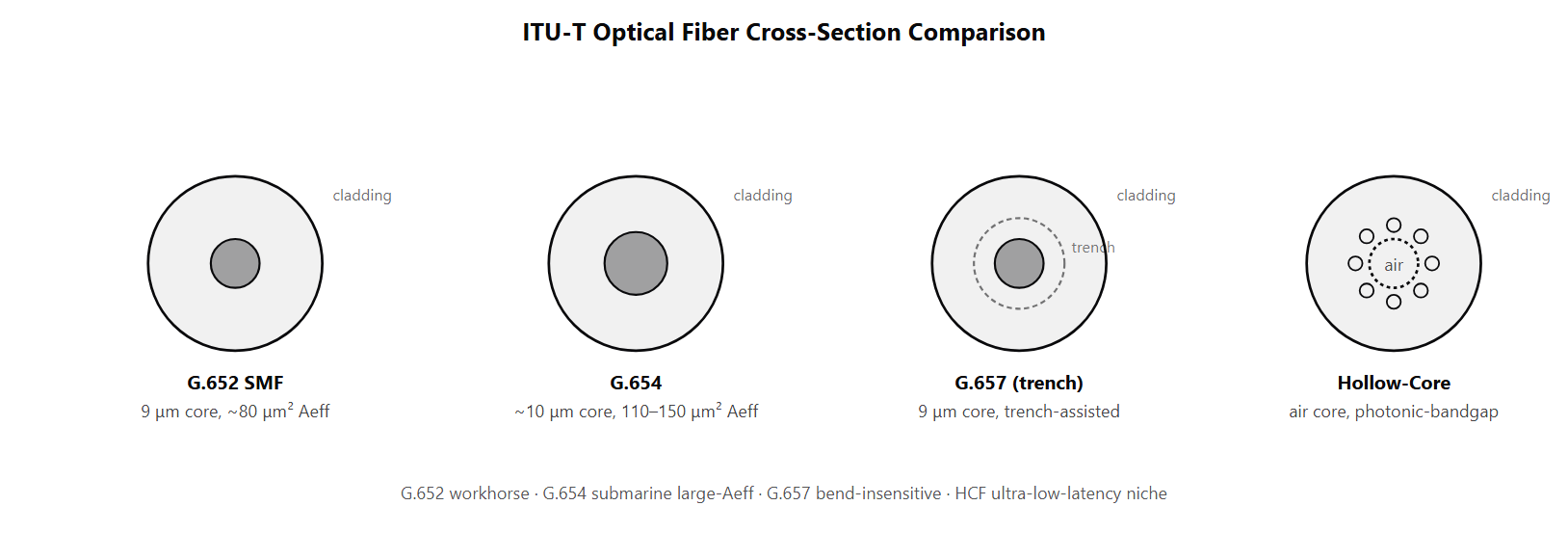
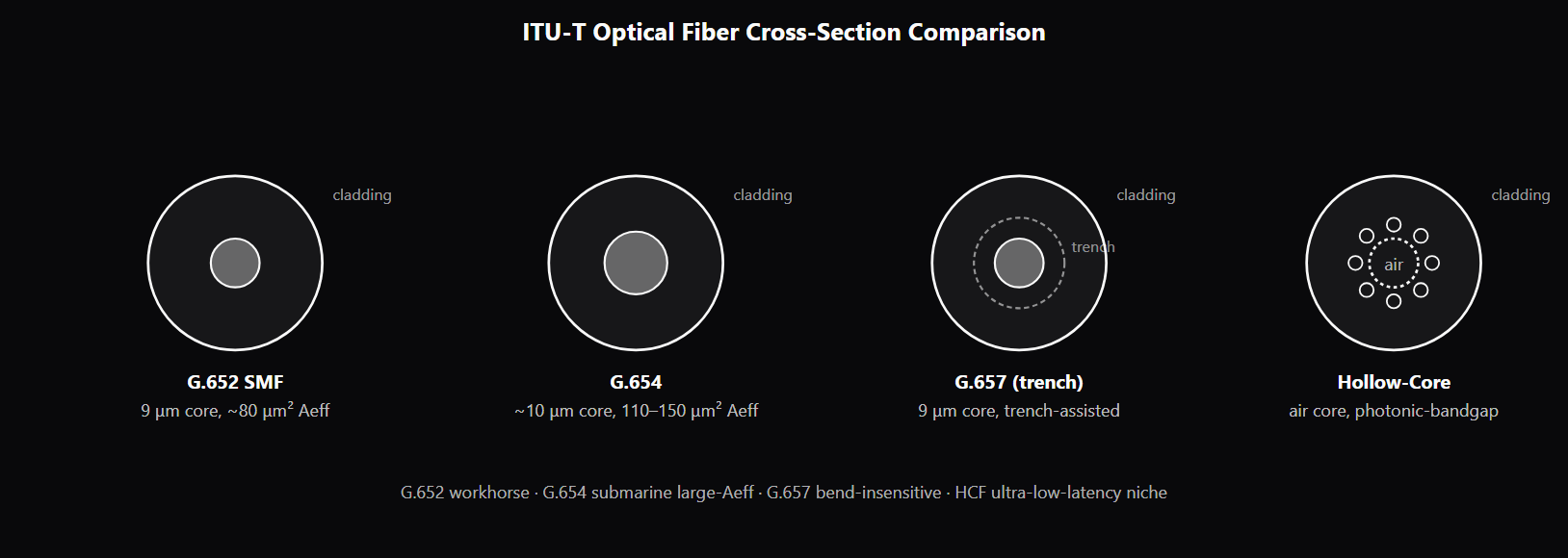
ITU-T G.65x fiber standards define the physical specifications of single-mode optical fiber for different deployment scenarios. Each standard targets a specific engineering trade-off between attenuation, effective area, bend tolerance, and cost. Operators specify fibers by ITU-T standard when ordering new cable so manufacturers and installers know exactly which spec to deliver. G.652 is the standard single-mode fiber used in the vast majority of deployed optical networks worldwide — terrestrial long-haul, metro, datacenter cabling, and access. The fiber has a 9 μm core diameter, 125 μm cladding, and effective area Aeff ≈ 80 μm². Attenuation is typically 0.18–0.20 dB/km at 1550 nm and 0.32–0.35 dB/km at 1310 nm. Sub-grades include G.652.B (the workhorse), G.652.C (low water-peak for E-band operation), and G.652.D (zero-water-peak across the full E-band). G.652 supports all common modulation formats, all standard amplification, and all wavelength ranges. G.654 is the large-effective-area fiber for long-haul terrestrial and submarine systems where Kerr nonlinearity is the binding constraint. The effective area is 110–150 μm² depending on sub-grade — significantly larger than G.652's 80 μm². The larger Aeff reduces optical-power density in the core, reducing nonlinear-effect penalty per unit launch power. This lets operators launch 1.5–2 dB more power without nonlinear penalty, which translates directly into more OSNR margin at the receive end of a long unregenerated link. G.654 is the standard fiber for transpacific and transatlantic submarine cables, and G.654.E is now used in many new terrestrial long-haul deployments at 400G+. G.657 is the bend-insensitive fiber designed for tight-routing applications — building risers, FTTH drops, datacenter cabling, equipment-rack patch cords. The fiber uses either a higher refractive-index delta or a trench-assisted index profile to confine the optical mode more tightly, so the mode does not escape under tight bends. Sub-grades specify progressively tighter bend tolerance: A1 at 15 mm radius, A2 at 10 mm, B3 at 7.5 mm. G.657 is designed to be compatible with G.652 at the connectivity level so splices and connectors work normally. Hollow-core fiber (HCF) is a microstructured fiber design where the optical mode is confined to a hollow air channel rather than a glass core. Light travels at c in air vs c/n in glass (n ≈ 1.45), so HCF has roughly 30% lower propagation delay than standard fiber — a meaningful latency advantage of ~165 μs per 100 km. HCF is currently niche because manufacturing complexity is high, attenuation has historically been higher than standard fiber, splice loss is higher, and cost is 5–10× standard fiber. Deployed applications include high-frequency trading metro links and ultra-low-latency financial datacenter interconnects. Recent HCF designs are pushing attenuation below G.652 levels; if this becomes consistent, HCF could move from niche to broader deployment. Multimode fiber (OM3, OM4, OM5) is the short-reach alternative for datacenter and enterprise applications under 300 m. The 50 μm core supports many optical modes, which costs modal-dispersion and limits reach but enables much cheaper source-coupling (less precise alignment). Multimode is the right choice for short links where the cost advantage outweighs the reach limit.
Why interviewers ask
Fiber-type choice is the most-asked deployment-engineering question in optical-transport interviews because fiber is the longest-lived piece of any optical-network deployment — it sits in the ground for 25–40 years — and the fiber-spec decision constrains every other system choice over that lifetime. A candidate who fluently navigates G.652 vs G.654 vs G.657 trade-offs and explains when each ITU-T standard is the right specification is showing the integrated cable-engineering and link-budget understanding that long-haul, submarine, datacenter, and FTTH roles require. The G.654 large-Aeff motivation is the deepest interview question. Strong candidates explain that submarine cables are nonlinearity-limited at high launch power, that the Aeff increase directly reduces nonlinear-effect penalty per unit launch power, and that the 1.5–2 dB launch-power gain translates into OSNR margin over a long submarine cable. Weak candidates name G.654 without understanding why it exists or when it wins over G.652. The G.657 bend-insensitive design is the access-network and datacenter-cabling question. Strong candidates explain that tight-routing applications (building risers, racks, drops) accumulate bend losses on G.652 — multiple dB across a building — which G.657 eliminates through tighter mode confinement. They can name the sub-grades and the bend-radius tolerance of each. The HCF question is the emerging-technology probe. Strong candidates explain the c/n vs c speed-of-light advantage, the resulting ~30% latency reduction, why HCF is still niche (manufacturing, attenuation historically, cost), and the high-frequency-trading and financial-DCI application where the latency premium is worth the cost. Candidates who do not know HCF exist or who dismiss it as theoretical miss a meaningful technology trend. The single-mode vs multimode question is the datacenter-cabling foundation. Candidates who can articulate why MMF wins on short-reach (cost, source-coupling) and why SMF wins on long-reach (reach, no modal dispersion) reveal basic understanding; candidates who treat both as interchangeable have not yet operated cable in different scenarios.
Common mistakes
The most common mistake is treating all single-mode fiber as the same. G.652, G.654, G.657 are different ITU-T specifications with different effective areas, bend tolerances, and attenuation profiles. The operator chooses per deployment scenario: G.652 for general terrestrial use; G.654 for submarine and OSNR-binding long-haul; G.657 for tight-routing access and datacenter. Candidates who collapse them into "SMF" miss the operator-level decision surface. A second gap is missing the nonlinear-effect motivation for G.654. The fiber's larger Aeff is specifically engineered to reduce Kerr-nonlinearity penalty, which is the binding constraint on launch power in long-haul and submarine systems. Candidates who describe G.654 as "lower-loss fiber" miss the engineering primary motivation; the attenuation is roughly comparable to G.652, but the Aeff advantage is the binding spec. A third gap is treating bend insensitivity as a marketing buzzword. G.657 is a real engineering spec with quantified bend-radius tolerance (A1 at 15 mm, A2 at 10 mm, B3 at 7.5 mm), and tight-routing applications need it because G.652 loses dB per tight bend. Candidates who dismiss G.657 as "G.652 with a label" have not worked at the access-network or datacenter-cabling level. A fourth gap is overstating or understating hollow-core fiber. Some candidates dismiss HCF as theoretical (it is deployed, in niche applications); others claim it is the universal future of optical fiber (it is not — manufacturing complexity, attenuation, and cost still keep it in specialized roles). Strong candidates know the latency advantage (~30%), the current attenuation/cost trade-offs, and the specific HFT and financial-DCI applications where it is deployed. A fifth gap is treating multimode as obsolete. MMF dominates short-reach datacenter and enterprise cabling because the cost advantage on source-coupling at 850 nm wavelengths is large; OM4 and OM5 fibers are actively being installed in new datacenters. The reach limit is the binding constraint, not technological obsolescence. Candidates who write off MMF have not faced datacenter cable-cost trade-offs. See /topics/dwdm-systems-explained for how fiber choice feeds into DWDM channel planning, and /topics/edfa-vs-raman-vs-soa for how the amplifier choice interacts with the fiber's nonlinearity profile.
ITU-T Optical Fiber Standards — Properties and Best Use
| Standard | Core/Aeff | Attenuation (1550 nm) | Bend Tolerance | Best Application |
|---|---|---|---|---|
| G.652 (SMF) | 9 μm / ~80 μm² | 0.18–0.20 dB/km | ~30 mm radius | Universal workhorse — terrestrial long-haul, metro, access |
| G.654 (large-Aeff) | ~10 μm / 110–150 μm² | 0.17–0.18 dB/km | ~30 mm radius | Submarine cables, terrestrial long-haul where nonlinearity binds |
| G.657.A1 / A2 (bend-insensitive) | 9 μm / ~80 μm² | 0.20–0.22 dB/km | 10–15 mm radius | Datacenter cabling, building risers, FTTH drops |
| G.657.B3 (tighter bend) | 9 μm / ~70 μm² | 0.22–0.25 dB/km | 7.5 mm radius | Very tight-routing applications |
| Hollow-Core Fiber (HCF) | air core ~20–30 μm | 0.18–0.5 dB/km | Tight (design-specific) | Ultra-low-latency niche (HFT, financial DCI) |
| Multimode (OM3/OM4/OM5) | 50 μm core | ~2.5 dB/km @ 850 nm | ~30 mm radius | Short-reach datacenter (under 300 m) |
Sample interview questions
- A submarine system designer is choosing between G.654 large-effective-area fiber and standard G.652 fiber for a new transpacific cable. What is the primary engineering reason for picking G.654, and what trade-off does it introduce?
- A. G.652 is always better than G.654; the standards differ only in name.
- B. G.654 has larger effective area (Aeff ≈ 110–150 μm² vs 80 μm² for G.652) which reduces the optical-power density in the fiber core. Lower power density means less Kerr-nonlinearity penalty per unit launch power, so the operator can launch more power per channel without nonlinear penalties — translating to better OSNR over the long unregenerated submarine reach. The trade-off is slightly higher cost per km and a small splice-loss penalty against G.652 (mismatched mode-field diameter at G.652-G.654 splices). ✓
- C. G.654 is only used in metro deployments, not submarine.
- D. G.654 is identical to G.652 but with a smaller core diameter.
Option B is correct. The fundamental engineering choice for submarine cables is OSNR-per-km, and the dominant constraint at high launch power is Kerr nonlinearity — the refractive index of silica varies with optical intensity, producing self-phase modulation (SPM), cross-phase modulation (XPM), and four-wave mixing (FWM). The Kerr-nonlinear coefficient scales inversely with effective area Aeff: doubling Aeff roughly halves the nonlinear penalty per unit launch power, letting the operator launch more power and improve OSNR. G.654 specifies large-Aeff submarine fiber: 110–150 μm² depending on the sub-grade (G.654.A, B, C, etc.). G.652 is the standard single-mode fiber with Aeff ≈ 80 μm². On a long submarine cable with ~100 amplifier spans, a 1.5–2 dB launch-power increase translates directly into 1.5–2 dB more OSNR margin at the receive end — significant. The trade-offs: - Cost per km is slightly higher for G.654 (specialized manufacturing) - Mode-field diameter (MFD) is larger, so splices to standard G.652 patch cords have a small loss penalty (typically 0.2–0.4 dB) - G.654 sometimes has slightly higher attenuation per km than G.652 (0.17–0.18 dB/km vs 0.18–0.20 dB/km — actually often comparable or slightly better for newer G.654.C variants) Operators typically use G.654 throughout the long submarine span and G.652 for terrestrial landing-side cabling, accepting the splice-loss penalty at the cable termination. Option A misses real differences. Option C is wrong — G.654 is the standard submarine-cable choice. Option D inverts the core-size relationship; G.654 has larger effective area, which usually corresponds to a slightly different index profile but not just a smaller core. Production reality: every new transpacific or transatlantic submarine cable built in the last decade specifies G.654 large-Aeff fiber; the OSNR-margin gain over G.652 is binding at the system-design level.
- A datacenter operator is deploying access fiber inside a building with tight bend radii (90° corners, cable bundling). Why is G.657 specifically called out for this use case?
- A. G.657 is identical to G.652; the naming is a marketing distinction.
- B. G.657 is engineered for bend insensitivity — it tolerates much tighter bend radii without loss penalty than G.652. G.652 typically loses 0.5–2 dB per 5 mm-radius bend; G.657.A1 tolerates 15 mm bends with sub-0.1 dB loss; G.657.A2 tolerates 10 mm; G.657.B3 tolerates 7.5 mm. This is achieved through tighter optical-mode confinement (trench-assisted index profile or higher core delta-n). G.657 fibers are designed to be physically deployable in datacenter racks, building risers, FTTH drops, and similar tight-routing scenarios without losing dB of margin at every bend. ✓
- C. G.657 is only used in submarine deployments.
- D. G.657 is identical to G.654 but with a smaller core.
Option B is correct. Standard G.652 fiber is optimized for low loss in a straight run; it does not tolerate tight bends well because the bending allows the optical mode to escape from the core into the cladding (radiation loss). The bend-loss curve is steep — a 5 mm bend can lose 1–2 dB on G.652, which is unacceptable in a datacenter where dozens of bends accumulate. G.657 specifies bend-insensitive single-mode fiber with sub-grades for progressively tighter bend tolerance: - G.657.A1 — tolerates 15 mm bend radius with sub-0.1 dB loss - G.657.A2 — tolerates 10 mm bend radius with sub-0.1 dB loss - G.657.B3 — tolerates 7.5 mm bend radius with sub-0.1 dB loss The engineering: bend insensitivity comes from tighter mode confinement in the fiber. G.657 fibers use either (a) a higher refractive-index delta between core and cladding (so the mode is more confined), or (b) a trench-assisted index profile (a depressed-index ring around the core that acts as a barrier preventing the mode from leaking out under bending). Both approaches achieve the bend tolerance at a small mode-field diameter cost. Compatibility: G.657 fibers are designed to be backward-compatible with G.652 at the connectivity level. Splices and connectors work normally; loss is a fraction of a dB. The fibers themselves can carry the same data rates and modulation formats as G.652. Datacenter, building riser, and FTTH last-mile cabling are the dominant G.657 applications. The bend insensitivity makes routing through tight spaces (riser shafts, equipment racks, building corners) practical without dB-level margin loss. Option A misses real engineering differences. Option C is wrong — submarine cables use G.654 large-Aeff for nonlinearity reasons, not bend tolerance. Option D confuses G.657 (bend-insensitive) with G.654 (large-area submarine). Production reality: most new building and datacenter deployments specify G.657.A1 or A2 as the standard; G.652 is being phased out in tight-routing applications.
- Hollow-core fiber (HCF) is increasingly proposed for ultra-low-latency applications. What is the latency advantage over standard silica fiber, and what makes HCF still niche?
- A. HCF has no latency advantage over standard fiber.
- B. In standard silica fiber, light propagates through the glass core at c/n (where n ≈ 1.45), so the group velocity is roughly c/1.5. In hollow-core fiber, light propagates through an air core at velocity very close to c (n ≈ 1.0), reducing propagation delay by roughly 30% — for a 100 km link this is about 165 μs less latency. HCF is niche because it has higher attenuation (~0.18–0.5 dB/km depending on design, vs 0.15–0.20 dB/km for G.652), much more complex manufacturing (microstructured photonic-bandgap or anti-resonant designs), higher splice losses, and is much more expensive per km. It is deployed only in applications where the latency saving justifies the cost — high-frequency trading metro links, ultra-low-latency financial datacenter interconnects. ✓
- C. HCF has the same latency as standard fiber but lower loss.
- D. HCF is only used in submarine cables.
Option B is correct. The latency advantage of HCF comes from the fact that light travels at c (the speed of light in vacuum) through air — significantly faster than through silica (c/n where n ≈ 1.45). Group-velocity calculation: t_propagation = L × n_group / c. For G.652 fiber over 100 km, t ≈ 100 km × 1.5 / c ≈ 500 μs (one-way). For HCF over the same distance, t ≈ 100 km × 1.0 / c ≈ 333 μs. Saving of ~165 μs per 100 km, or 33% reduction. Why HCF is still niche: - Manufacturing complexity: HCF uses microstructured designs (photonic-bandgap or anti-resonant geometries) where the optical mode is confined to a hollow air channel surrounded by a periodic structure of glass/air. Manufacturing tolerances are tight, and yield is lower than for solid-core fiber - Attenuation: typical HCF achieves 0.18–0.5 dB/km, sometimes worse, vs 0.15–0.20 dB/km for G.652. The exception is the latest hollow-core designs which are pushing below standard fiber loss - Splice and connector loss: splicing hollow-core to standard fiber requires specialized mode-converter interfaces; per-splice loss is higher (typically 0.5–1.5 dB) - Cost per km: significantly higher than G.652 — sometimes 5–10× more The applications where HCF wins despite these limits: - High-frequency trading metro links between financial exchanges, where 100 μs of latency advantage is worth millions of dollars - Ultra-low-latency financial datacenter interconnects - Some emerging quantum-networking applications where the dispersion characteristics of HCF are useful HCF is one of the active research areas in optical fiber, and the per-km loss has been dropping. If it crosses below G.652 attenuation while maintaining the latency advantage, it could become a much broader-market technology. Option A misses the latency mechanism. Option C inverts the situation — HCF has both latency advantage and (historically) higher loss. Option D is wrong; submarine cables use G.654 standard solid-core fiber. Production reality: HCF deployments are still in the millions-of-meters scale rather than the billions-of-meters of standard fiber, concentrated in specific high-value low-latency applications.
Frequently asked questions
- What is G.652 fiber?
- G.652 is the ITU-T standard for single-mode fiber used in the vast majority of deployed optical networks worldwide — terrestrial long-haul, metro, access, and datacenter cabling. The fiber has a 9 μm core diameter, 125 μm cladding, and effective area Aeff ≈ 80 μm². Attenuation is typically 0.18–0.20 dB/km at 1550 nm and 0.32–0.35 dB/km at 1310 nm. The standard has multiple sub-grades: G.652.B is the workhorse for most deployments; G.652.D is the "zero-water-peak" variant with low attenuation across the full E-band (1360–1460 nm). G.652 supports all standard modulation formats, all standard amplification (EDFA), and all wavelength ranges (O, E, S, C, L bands).
- What is G.654 fiber and when is it used?
- G.654 is a large-effective-area, low-attenuation fiber designed for long-haul terrestrial and submarine systems where Kerr nonlinearity is the binding constraint. The effective area Aeff is 110–150 μm² depending on the sub-grade (G.654.A through G.654.E), compared to G.652's 80 μm². The larger Aeff reduces optical power density in the core, which reduces nonlinear-effect penalty per unit launch power — letting operators launch 1.5–2 dB more power without nonlinear penalty. Attenuation is also slightly lower than G.652 for some sub-grades (0.17 dB/km vs 0.18–0.20 dB/km). The trade-offs are slightly higher cost per km and a small splice-loss penalty against G.652. G.654 is the standard choice for transpacific and transatlantic submarine cables; G.654.E is used in some terrestrial long-haul.
- What is G.657 bend-insensitive fiber?
- G.657 is the ITU-T standard for bend-insensitive single-mode fiber designed for tight-routing scenarios — building risers, FTTH drops, datacenter cabling, equipment-rack patch cords. The fiber uses either a higher refractive-index delta or a trench-assisted index profile to confine the optical mode more tightly, so the mode does not escape into the cladding under tight bends. Sub-grades specify progressively tighter bend tolerance: G.657.A1 tolerates 15 mm bend radius with sub-0.1 dB loss; G.657.A2 tolerates 10 mm; G.657.B3 tolerates 7.5 mm. G.657 fibers are designed to be compatible with G.652 at the connectivity level — splices and connectors work normally with sub-dB loss penalties.
- What is hollow-core fiber (HCF)?
- Hollow-core fiber is a fiber design where the optical mode is confined to a hollow air channel rather than a glass core, achieved through microstructured photonic-bandgap or anti-resonant geometries that confine the mode using a periodic structure of glass and air around the central hollow region. The latency advantage is roughly 30% lower propagation delay than standard silica fiber (because light travels at c in air vs c/n in glass, with n ≈ 1.45). HCF is niche because manufacturing complexity is high, attenuation has historically been higher than standard fiber (0.18–0.5 dB/km, though latest designs are competitive with G.652), splice loss is higher, and cost is 5–10× standard fiber. Deployed applications include high-frequency trading metro links and ultra-low-latency financial datacenter interconnects where the latency saving justifies the cost.
- What is the difference between single-mode and multimode fiber?
- Single-mode fiber (SMF) has a narrow core (8–10 μm) that supports only one optical mode at typical telecom wavelengths (1310, 1550 nm). The single mode means no modal dispersion — all light travels at the same velocity, so pulses do not spread. SMF supports long reaches (km to thousands of km) at high data rates. Multimode fiber (MMF) has a wider core (50 μm or 62.5 μm) that supports many optical modes; the modes travel at slightly different velocities, producing modal dispersion that limits reach to hundreds of meters at multi-Gb/s rates. MMF is cheaper to source-couple (less precise alignment required), so it dominates short-reach datacenter and enterprise applications where reach is under 300 m. SMF dominates everything beyond.
- What is fiber attenuation and what causes it?
- Fiber attenuation is the loss of optical power per unit length, expressed in dB/km. In standard silica fiber at 1550 nm, attenuation is roughly 0.18–0.20 dB/km. The sources: (1) Rayleigh scattering — random density fluctuations in the silica matrix scatter a fraction of the light; this is the dominant intrinsic loss mechanism at typical telecom wavelengths. (2) Water absorption (OH peak around 1383 nm) — bands of high loss in older fibers; G.652.D and newer specifications minimize this. (3) Infrared absorption — silica's intrinsic vibrational absorption rises sharply above 1700 nm. The 1550 nm window minimizes the sum of these losses and is why C-band DWDM operates there. Total link loss for a 100 km span at 0.20 dB/km is ~20 dB, the per-span loss budget that EDFAs are sized to replace.
- What is polarization-mode dispersion (PMD)?
- PMD is the dispersion that comes from random birefringence in real fiber — small variations in the core's circular symmetry along the fiber's length cause the two orthogonal polarization modes to travel at slightly different velocities, spreading a pulse in time. PMD accumulates with the square root of fiber length (random-walk statistics), unlike chromatic dispersion which accumulates linearly. Modern fiber has very low PMD (under 0.1 ps/√km), but older deployed fiber can have several ps/√km, which becomes a real impairment for very long reaches at high baud rates. Coherent DSP can compensate PMD digitally as part of polarization de-multiplexing (the CMA equalizer separates the two polarization streams and undoes the PMD-induced delay), so PMD is much less of a reach-limiter for coherent systems than for the older direct-detection era when it was a hard reach constraint.
- How does fiber type affect reach for 400G coherent links?
- At 400G coherent (typically 64 GBaud DP-16QAM with 20% FEC), the reach limit comes from OSNR margin and is constrained by amplifier noise, fiber type, and nonlinear effects. On standard G.652, unregenerated reach is typically 1500–2500 km depending on amplifier choice and span planning. On G.654 large-Aeff fiber, the nonlinear penalty is reduced, allowing higher launch power and 2000–3500 km unregenerated reach — a 30–50% reach extension at the cost of fiber-and-system upgrade. On hollow-core fiber (where deployed), the latency advantage matters more than the reach, but the fiber attenuation usually limits reach to similar or shorter than G.652. Fiber choice is one of the major levers operators use to extend reach without regeneration; G.654 is increasingly deployed on new long-haul and submarine routes specifically to maximize unregenerated reach at 400G+ rates.
Related topics
Siblings
- DWDM Systems Explained: C-Band, L-Band, and the 400G/800G Era
- Optical Fiber Impairments Explained: CD, PMD, Nonlinearity
- EDFA vs Raman vs SOA: Optical Amplifier Comparison
- PON Evolution: GPON → XGS-PON → TWDM-PON → 50G-PON
- ROADM & Wavelength Switching Explained: WSS, Degrees, CDC
- Optical Engineer Interview Signals: What Interviewers Probe
Essential AI-Native Skills for Optical Fiber Standards: G.652 vs G.654 vs G.657 vs Hollow-Core
Modern engineering work increasingly uses AI tools for design and code review, debugging, documentation, test and testbench generation, and workflow automation. The goal is not to let AI replace engineering judgment — it is to move faster while keeping verification discipline.
- Use AI to explain unfamiliar code, logs, waveforms, datasheets, or test failures.
- Break large problems into small, reviewable steps you can verify independently.
- Ask AI for hypotheses, then validate them against tests, measurements, simulations, or lab data.
- Version-control your analysis scripts, testbenches, and configs — keep changes small and reviewable.
- Document your assumptions, design tradeoffs, and debugging decisions.
- Verify AI output before trusting it: run the checks that fit the domain — unit tests, linters, simulations, or bench/lab measurements.
- Review AI output for correctness, edge cases, and real-world consequences.
Optical Fiber Standards: G.652 vs G.654 vs G.657 vs Hollow-Core — coming to the question bank
The adaptive practice engine is already live for core wireless, RF, and ML systems. Optical Fiber Standards: G.652 vs G.654 vs G.657 vs Hollow-Core isn't covered in the question bank yet — get notified when it's added.