DWDM Systems Explained: C-Band, L-Band, and the 400G/800G Era Interview Prep
DWDM systems explained — ITU-T frequency grid, 50 GHz vs 100 GHz spacing, C-band vs L-band, flex-grid, superchannels, and 400ZR/800ZR pluggable optics.
Quick answer
DWDM (Dense Wavelength Division Multiplexing) is the optical-transport technology that carries many independent high-rate channels on the same fiber by assigning each channel a distinct wavelength on the ITU-T frequency grid.
DWDM is the single biggest deployed-network topic in optical-transport interviews because it integrates every other optical engineering layer — fiber, amplifiers, transceivers, modulation formats, dispersion, nonlinearities, and ROADMs — into one operational system.
Editorial review
Written by
CompoundLearn editorial team
Wireless / RF / hardware engineering
Reviewed by
CompoundLearn editorial team
Wireless / RF / hardware engineering
Last reviewed
Built from curated topic maps, editorial validation, and subject-matter review so the page stays aligned with the interview intent and the current content pipeline.
What it is
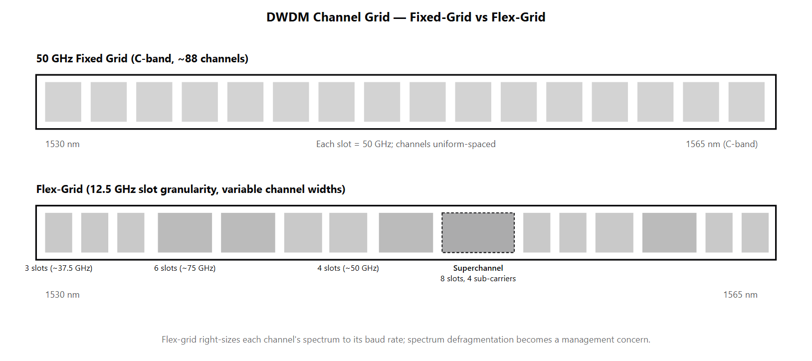
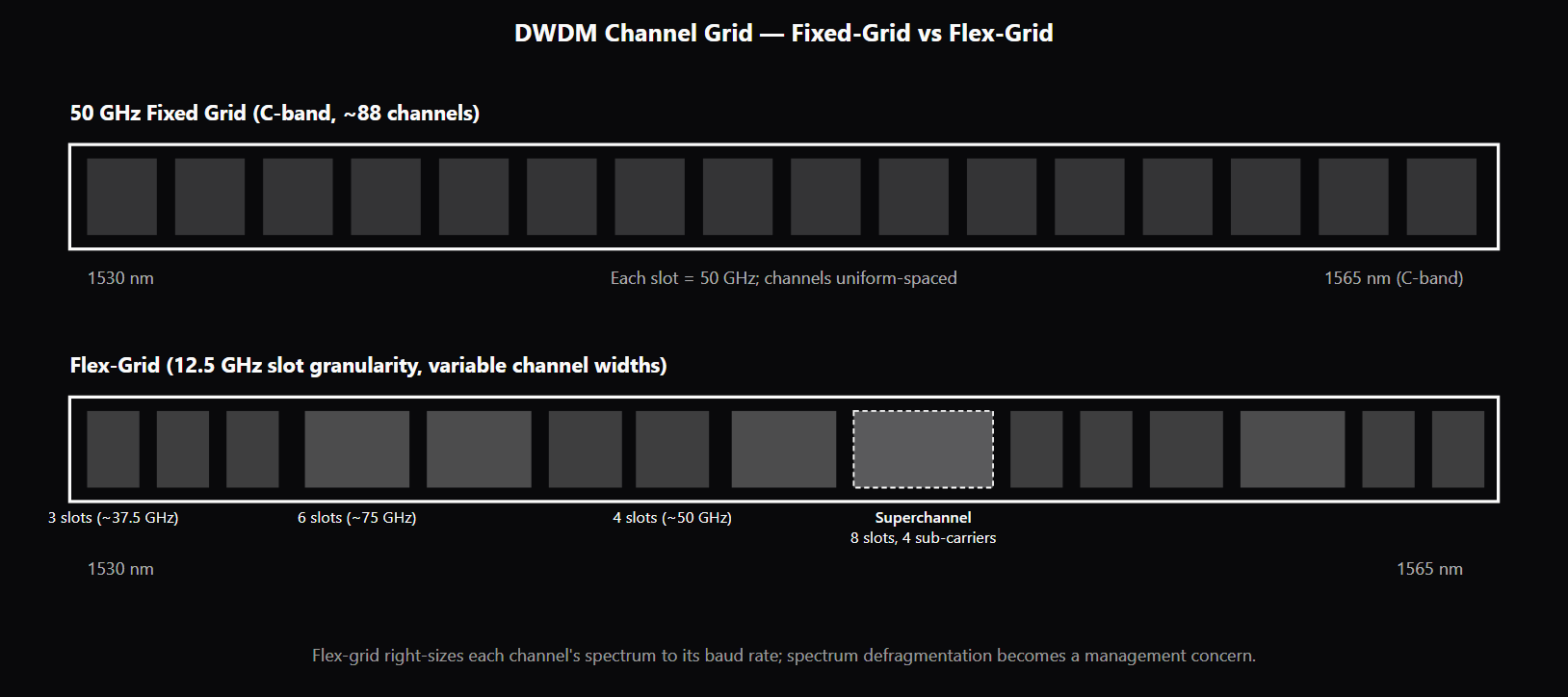
DWDM (Dense Wavelength Division Multiplexing) is the optical-transport technology that carries many independent high-rate channels on the same fiber by assigning each channel a distinct wavelength on the ITU-T frequency grid. A 2026-era DWDM line system typically carries 80–96 channels in the C-band at 50 GHz spacing plus a comparable count in the L-band, with each channel carrying 100–800 Gb/s of coherent-encoded payload — aggregating to tens of Tb/s per fiber pair. DWDM is the workhorse of long-haul, regional, metro, and submarine optical transport, and is increasingly the technology of choice for high-throughput data-center interconnect (DCI) between hyperscalers. The ITU-T frequency grid (G.694.1) defines the channel anchor frequencies. The reference is 193.1 THz (about 1552.52 nm in the C-band), with grid anchors spaced at 100 GHz, 50 GHz, 25 GHz, 12.5 GHz, and finer increments. The 50 GHz fixed-grid configuration is the most common deployed format because it balances per-channel spectrum (enough for 32 GBaud channels at 200G–400G with comfortable guard band) against C-band capacity (~88–96 channels). The 100 GHz fixed-grid is used in older systems and in deployments where channel rates are low enough to leave significant unused margin per channel. The C-band spans roughly 1530–1565 nm and aligns with the natural gain peak of erbium-doped fiber amplifiers (EDFAs); this is why C-band became the dominant DWDM band early. The L-band spans roughly 1565–1625 nm and requires a differently-engineered EDFA. Modern high-capacity systems deploy C+L together to roughly double per-fiber capacity from C-only at the cost of significant added system complexity: separate EDFA chains for each band, per-band gain-tilt management, and inter-band Raman crosstalk control because the C-band can pump energy into the L-band via stimulated Raman scattering at high power levels. Flex-grid is the upgrade path beyond fixed-grid for the 400G+ era. It divides the band into 12.5 GHz slots and allocates each channel a contiguous block of slots sized to its spectral width. A 32 GBaud DP-16QAM channel uses ~3 slots (~37.5 GHz); a 64 GBaud DP-64QAM channel uses ~6 slots (~75 GHz); a multi-carrier superchannel might span 8 or more slots. Flex-grid is necessary because channels above 64 GBaud no longer fit a 50 GHz fixed-grid slot, and right-sizing each channel's spectrum is the only way to keep band utilization high. The operational cost is real: spectrum defragmentation becomes a management procedure, ROADMs need variable-passband WSS, and the control plane must track per-channel slot allocation. 400ZR (OIF coherent 400G pluggable) and 800ZR (the 800G follow-on) are the architectural shift that puts coherent DWDM transceivers directly into router and switch front panels — same QSFP-DD and OSFP form factors as short-reach grey optics, but with coherent DWDM modulation and reach up to 120 km amplified or unamplified depending on variant. This is the move sometimes called "router-integrated coherent" or "IPoDWDM" that is collapsing the historical IP/optical layering.
Why interviewers ask
DWDM is the single biggest deployed-network topic in optical-transport interviews because it integrates every other optical engineering layer — fiber, amplifiers, transceivers, modulation formats, dispersion, nonlinearities, and ROADMs — into one operational system. A candidate who fluently navigates ITU-T grid spacing, C-band vs L-band trade-offs, flex-grid versus fixed-grid, superchannel design, and 400ZR/800ZR pluggables is showing the integrated systems understanding that staff and principal optical-transport engineering roles require. The 50 GHz vs 100 GHz fixed-grid trade-off is probed because it is the operator-level decision that every DWDM upgrade hits. Strong candidates can explain how the channel's spectral width must fit the slot (with guard band), why 64 GBaud channels need 75 GHz or 100 GHz slots if fixed-grid is used, and when flex-grid becomes necessary. C+L operation is the deep-cut interview topic. Many candidates know that C-band exists; fewer can explain why L-band needs a separate EDFA chain, what inter-band Raman crosstalk is, and how operators manage the gain-tilt and power-balance complexity that comes with running both bands. The C+L decision is where senior optical engineers earn their salaries because the capacity-versus-complexity trade-off is non-trivial. Flex-grid management is probed because it is the operationally new piece. Candidates who name flex-grid without explaining 12.5 GHz slot granularity, defragmentation, or the variable-passband WSS requirement have heard of the technology but not deployed it. Strong candidates describe the SDN-based control-plane approach that most operators take to flex-grid management. 400ZR / 800ZR pluggable architecture is the architectural-shift question. Strong candidates explain that putting coherent DWDM into router/switch front panels collapses the traditional IP/optical layering (no separate transponder shelf), changes the operations model (the router team owns the optics), and shifts where coherent-transceiver innovation happens (pluggable form factors with strict power and thermal budgets, increasingly silicon-photonics-based). Candidates without exposure to this architectural shift miss a major industry trend.
Common mistakes
The most common mistake is treating DWDM as one homogeneous "lots of wavelengths" technology without recognizing the architectural choices that define a specific deployment: fixed-grid vs flex-grid, 50 GHz vs 100 GHz vs variable, C-only vs C+L, fixed transponder vs pluggable coherent. Candidates who collapse all of these into "DWDM" miss the operator-level decisions that distinguish deployed systems. A second gap is misunderstanding the channel-versus-slot relationship at high baud rates. A 64 GBaud channel does not fit in a 50 GHz slot; either the grid moves to flex-grid (variable slot width) or the system goes to 75 GHz / 100 GHz fixed-grid with reduced capacity. Candidates who claim "all DWDM is 50 GHz" or who ignore the spectral-width constraint at high baud rates have not worked at the channel-plan level. A third gap is missing the C+L complexity. L-band is not "just more C-band" — it requires a different EDFA design, separate gain-tilt management, and inter-band crosstalk control. Operators do C+L specifically because it roughly doubles per-fiber capacity at sub-2× cost, but the system complexity is real. Candidates who describe C+L as "C-band but at longer wavelength" miss the engineering depth. A fourth gap is conflating flex-grid with elastic optical networks or any other "flexible" buzzword. Flex-grid specifically means the 12.5 GHz slot granularity with per-channel variable allocation defined in the ITU-T G.694.1 supplement. It enables right-sized channel allocation but introduces spectrum defragmentation, variable-passband WSS, and SDN-based control-plane complexity. Candidates who use the term without naming the slot granularity or the defragmentation problem have not understood the operational model. A fifth gap is missing the 400ZR / 800ZR pluggable shift. Coherent DWDM transceivers in router/switch front panels is the architectural shift that is collapsing IP/optical layering and changing the operations model. Candidates who describe DWDM as if it always required a separate transponder shelf miss the move toward router-integrated coherent. See /topics/coherent-optical-detection for the receiver-side architecture, /topics/edfa-vs-raman-vs-soa for the amplifier-side context, and /topics/optical-fiber-standards-itu for the fiber types that newer DWDM deployments specify.
DWDM Grid Options — Fixed vs Flex
| Grid Type | Channel Spacing | Channels in C-band | Typical Channel Rate | Best Application |
|---|---|---|---|---|
| 100 GHz fixed | 100 GHz | ~44 | 100G coherent or older | Legacy backbones, low utilization |
| 50 GHz fixed | 50 GHz | ~88–96 | 200G–400G coherent at 32 GBaud | Most deployed DWDM |
| 25 GHz fixed | 25 GHz | ~176 | Low-rate channels, NB-DWDM access | Specialty / access |
| Flex-grid (12.5 GHz slots, variable width) | Variable per channel | Variable | 400G–1.6T, superchannels | 400G+ backbone, C+L systems |
Sample interview questions
- A 100 GHz fixed-grid DWDM line system carries 32 GBaud DP-16QAM (200G) channels. Why does moving to a 50 GHz fixed-grid double the channel count without changing the line system fundamentally?
- A. 50 GHz spacing halves the per-channel data rate, so the total capacity stays the same.
- B. 50 GHz spacing fits twice as many ITU-T grid channels in the C-band. A 32 GBaud channel occupies roughly 32–37 GHz of spectrum (signal plus a few GHz of guard band), so it fits inside a 50 GHz slot. The line system reuses the same EDFAs, filters, and ROADMs; only the channel plan changes. This is the classic upgrade path from 100 GHz spacing (~44 channels in C-band) to 50 GHz spacing (~88 channels in C-band). Higher baud rates (64+ GBaud) no longer fit 50 GHz and drive the move to 75/100 GHz fixed-grid or flex-grid. ✓
- C. 50 GHz spacing requires entirely new optical filters and amplifiers.
- D. 50 GHz spacing only works with on-off-keyed modulation, not coherent.
Option B is correct. The ITU-T frequency grid (G.694.1) defines channel anchors at 50 GHz, 100 GHz, and other spacings. A 100 GHz grid in the C-band (1530–1565 nm, roughly 4400 GHz of usable bandwidth) accommodates ~44 channels; a 50 GHz grid doubles that to ~88. Moving to 50 GHz spacing roughly doubles capacity per fiber without changing the underlying line system — same EDFAs, same ROADMs, same fiber plant. The fit constraint at 50 GHz is that the channel's spectral footprint must fit in 50 GHz minus a guard band. A 64 GBaud signal with raised-cosine pulse shaping (roll-off 0.1–0.2) has a 3-dB optical bandwidth around 64–67 GHz — too wide for 50 GHz spacing without pre-DSP spectral shaping. But Nyquist pulse shaping (sharp rectangular spectrum) at 32 GBaud fits 50 GHz comfortably; 32 GBaud DP-16QAM is 200G; 32 GBaud DP-QPSK is 100G. Higher baud rates (64+ GBaud) need 75 GHz or 100 GHz fixed-grid slots, which is why flex-grid (variable-slot allocation) was added — see /topics/optical-fiber-impairments and the flex-grid sections of this page. Option A treats line rate and channel rate as one number — they are not. Option C is wrong — the same EDFAs and ROADMs work, only the channel-filter shaping needs to support 50 GHz selectivity. Option D is wrong — 50 GHz fixed-grid is the standard for coherent operation. Production reality: 50 GHz fixed-grid is the most common deployed DWDM configuration; flex-grid is the upgrade path for systems carrying 600G+ per channel where 50 GHz no longer fits.
- What is the operational reason for using L-band amplification in addition to C-band, and why is C+L not just "twice the C-band"?
- A. L-band is identical to C-band; the naming is just a regulatory distinction.
- B. C-band (~1530–1565 nm) and L-band (~1565–1625 nm) together roughly double the per-fiber capacity available from C-band alone. But the bands cannot share the same EDFA — erbium-doped fiber amplifiers have peak gain around 1530–1560 nm, and L-band EDFAs use longer or differently doped fiber to provide gain at the longer wavelengths. Operators using C+L deploy separate amplifier chains, often combined by interleavers, and must manage two gain spectra plus inter-band power balance. The capacity roughly doubles but the system complexity and cost grow more than 2×. ✓
- C. L-band is only used in submarine deployments; terrestrial DWDM uses C-band exclusively.
- D. C+L operation cancels nonlinear effects entirely.
Option B is correct. The C-band spans roughly 1530–1565 nm (about 4.4 THz of optical bandwidth) and is the band where erbium-doped fiber amplification has its strongest, flattest gain. L-band spans roughly 1565–1625 nm (another ~4.8 THz of optical bandwidth) and requires a differently-engineered EDFA (longer erbium-doped fiber and/or modified composition) because erbium's natural gain peak is centered in the C-band. C+L deployment roughly doubles per-fiber capacity from the ~17–24 Tb/s typical of C-only systems to ~35–45 Tb/s C+L. But the system is not "twice the C-band" — operators must: - Deploy separate EDFA chains for C and L bands, often interleaved - Manage two gain spectra and the gain tilt of each band independently - Balance inter-band power to control nonlinear Raman crosstalk (the higher-power C-band can transfer energy to L-band via stimulated Raman scattering) - Coordinate channel-power equalization across both bands The cost and complexity grow more than 2×, but capacity per fiber roughly doubles, so the per-bit cost still improves enough to justify the upgrade in fiber-constrained routes (urban backbones, submarine systems, dense metro). New deployments increasingly default to C+L from day one rather than upgrading later. Option A misses the gain-spectrum distinction. Option C is wrong — both terrestrial and submarine deployments use C+L. Option D is wrong — nonlinear effects accumulate within each band and inter-band Raman crosstalk is an added complication. Production reality: 800G-era deployments increasingly assume C+L as a baseline; the new fiber types (G.654, hollow-core) provide larger effective area and lower nonlinearity to better support C+L power budgets. See /topics/optical-fiber-standards-itu for the fiber-side context.
- A flex-grid DWDM system replaces fixed-grid spacing with variable-slot allocation. What does this enable, and what new operational complexity does it introduce?
- A. Flex-grid is identical to fixed-grid; the naming is a marketing distinction.
- B. Flex-grid divides the band into 12.5 GHz "slots" (the granularity defined by ITU-T G.694.1 supplement) and allocates each channel a variable number of contiguous slots based on its spectral width. A 32 GBaud DP-16QAM channel uses ~3 slots (~37.5 GHz); a 64 GBaud DP-64QAM channel uses ~6 slots (~75 GHz); a superchannel grouping multiple carriers might use 8+ slots. This enables right-sizing each channel's spectrum to its baud rate and capacity, packing the band more efficiently. The new complexity: spectrum management becomes a non-trivial allocation problem ("spectrum defragmentation"), ROADM filters must support variable passbands, and channel adds/drops must avoid creating un-allocatable gaps. ✓
- C. Flex-grid only works at FR2 frequencies.
- D. Flex-grid eliminates the need for ROADMs.
Option B is correct. Flex-grid (ITU-T G.694.1 supplement) replaces the fixed-50-GHz or fixed-100-GHz grid with a finer-granularity slot architecture: the band is divided into 12.5 GHz slots, and each channel is allocated a contiguous block of slots sized to its spectral width. A 32 GBaud DP-16QAM channel needs roughly 3 slots (~37.5 GHz). A 64 GBaud DP-64QAM channel needs roughly 6 slots (~75 GHz). A superchannel — multiple sub-carrier signals jointly modulated — might span 8 or more slots. Why flex-grid is a real win at 400G+: at 64 GBaud and higher, the channel's spectral width exceeds 50 GHz, so it doesn't fit a 50 GHz fixed-grid slot anyway. Fixed-grid 100 GHz slots waste capacity for narrower channels; flex-grid packs both wide and narrow channels into the band without wasted spectrum. The new operational complexity: - Spectrum becomes a fragmentation problem. Channels added at different times and sizes can leave un-allocatable gaps. Spectrum defragmentation procedures (similar to disk defrag) shift channels to consolidate free spectrum. - ROADM filters must support variable passbands. Wavelength-Selective Switches (WSS) with multi-channel-spectrum capability replace fixed-grid WSS. - The management plane must track per-channel slot allocation; SDN-based optical control is increasingly the way operators run flex-grid systems. Option A misses real architectural differences. Option C is wrong — flex-grid is an optical-domain concept, not an FR concept. Option D is wrong — flex-grid actually requires more sophisticated ROADMs, not none. See /topics/roadm-wavelength-switching (queued) for the ROADM-side context. Production reality: most newly-deployed 400G-and-above DWDM is flex-grid; mixed-grid migrations (fixed + flex on the same fiber) are common as operators upgrade segment-by-segment.
Frequently asked questions
- What is DWDM?
- DWDM (Dense Wavelength Division Multiplexing) is the optical-transport technology that carries many independent channels on the same fiber by assigning each channel a distinct wavelength (equivalently, a distinct frequency slot in the ITU-T frequency grid). A typical DWDM line system in 2026 carries 80–96 channels in the C-band at 50 GHz spacing, plus another 80+ channels in the L-band, with each channel carrying 100–800 Gb/s of payload depending on the coherent transceiver generation. The aggregate per-fiber capacity reaches 20–45 Tb/s for C-only systems and up to 70 Tb/s for C+L systems. DWDM is the workhorse of long-haul, regional, metro, and submarine optical transport, and increasingly of high-throughput DCI (data-center interconnect) links between hyperscalers.
- What is the difference between DWDM and CWDM?
- CWDM (Coarse Wavelength Division Multiplexing) uses wider channel spacing (typically 20 nm, ~2500 GHz) and looser laser-wavelength tolerances; this lowers the optical filter and laser cost but limits the channel count to about 18 channels across the S+C+L bands. DWDM uses narrow channel spacing (50 GHz or 100 GHz, occasionally 25 GHz) and tightly-controlled DFB or external-cavity lasers; this enables 80+ channels per band but raises the per-channel cost. CWDM dominates short-reach metro-access deployments (~80 km) where high channel count is not needed; DWDM dominates everywhere capacity matters.
- What is the ITU-T frequency grid?
- The ITU-T G.694.1 recommendation defines the channel anchor frequencies for DWDM. The grid is defined in frequency (not wavelength) with anchors spaced at fixed intervals: 100 GHz, 50 GHz, 25 GHz, 12.5 GHz (for flex-grid), and finer. The reference frequency is 193.1 THz (about 1552.52 nm in the C-band). 50 GHz grid is the most common fixed-grid deployment because it balances per-channel spectrum against C-band capacity (about 96 channels in the C-band). 100 GHz grid is used in older systems and in deployments where the channel rate is low enough to leave usable margin. Flex-grid (12.5 GHz granularity with variable slot widths) is the upgrade path for 400G+ systems where channels exceed 50 GHz spectral width.
- What is the difference between C-band and L-band?
- The C-band spans roughly 1530–1565 nm (~4.4 THz of optical bandwidth) and is the band where erbium-doped fiber amplifiers have their natural gain peak. The L-band spans roughly 1565–1625 nm (~4.8 THz) and requires a differently-engineered EDFA (longer or differently-doped erbium fiber) because erbium's gain falls off above 1565 nm. C-band alone supports about 20–24 Tb/s per fiber at 400G channels on a 50 GHz grid; C+L roughly doubles that to 35–45 Tb/s by using both bands. C+L operation requires separate EDFA chains, separate gain-tilt management per band, and careful inter-band Raman crosstalk control (the C-band can pump energy into L-band channels via stimulated Raman scattering).
- What is a flex-grid DWDM system?
- Flex-grid replaces fixed channel spacing with variable-slot allocation. The band is divided into 12.5 GHz slots (the granularity defined in the ITU-T G.694.1 supplement), and each channel is allocated a contiguous block of slots sized to its spectral width. A 32 GBaud channel uses ~3 slots; a 64 GBaud channel uses ~6 slots; a superchannel (multiple sub-carriers jointly modulated) might span 8 or more slots. Flex-grid is the standard for 400G+ DWDM because channels above 64 GBaud do not fit a 50 GHz fixed-grid slot. The operational complexity is non-trivial: spectrum defragmentation becomes a real management procedure, ROADMs need variable-passband WSS, and the management plane must track per-channel slot allocation across the line system.
- What is a superchannel?
- A superchannel groups multiple closely-spaced optical carriers into a single jointly-managed channel that is added and dropped as one unit. A typical superchannel might combine 4 carriers of 32 GBaud DP-16QAM (each 200 Gb/s) into a 800 Gb/s superchannel, or a similar arrangement with PCS-QAM at 1.6 Tb/s. The carriers are spaced at Nyquist sub-channel spacing (sometimes called Nyquist WDM, or N-WDM) so they pack tightly with minimal guard band. Superchannels exist because (a) coherent transceiver line rates increasingly exceed what a single carrier can carry per Hz under deployed OSNR, and (b) managing the carriers as one unit simplifies ROADM and management-plane operation. The trade-off is reduced flexibility (the operator commits the full superchannel slot rather than per-carrier allocation), which is fine for high-utilization backbone routes.
- How are 400ZR and 800ZR pluggable transceivers related to DWDM?
- 400ZR is the OIF-defined coherent pluggable transceiver standard for 400G over DWDM, packaged in QSFP-DD or OSFP form factor with reach typically up to 120 km amplified or unamplified depending on the variant. 800ZR/800ZR+ is the follow-on standard for 800G coherent in similar form factors, with reach extensions for amplified spans. The significance is that these pluggables put coherent DWDM transceivers into router/switch front panels — the same boxes that historically used grey (non-coherent) short-reach optics now plug in coherent DWDM optics directly without a separate transponder shelf. This is the architectural shift sometimes called "router-integrated coherent" or "IPoDWDM" that is collapsing the traditional IP/optical layering. Note this is a different debate from intra-datacenter switch fabrics, where the packaging question is whether to keep the same QSFP-DD/OSFP pluggables at all or move the optical engine onto the switch ASIC — see /topics/cpo-vs-pluggable-optics.
- How does channel-power equalization work across cascaded amplifiers?
- A DWDM line system passes through many EDFAs in series. Each EDFA has a gain that varies slightly with wavelength (gain tilt) and with input power (gain saturation effects). After 5–10 cascaded EDFAs, the channel power across the band can be tilted by several dB — some channels arrive much stronger than others, which causes nonlinear-effect imbalance and Q-factor degradation. Channel-power equalization uses either (a) variable optical attenuators (VOAs) per channel inside each ROADM degree, or (b) wavelength-selective switches (WSS) that can apply per-channel attenuation. The control plane typically runs a power-equalization loop that monitors per-channel power at each ROADM, calculates the required per-channel attenuation, and applies it to keep channel powers within a target range across the whole line system. See /topics/edfa-vs-raman-vs-soa for the amplifier-side context.
Related topics
Siblings
- Coherent Optical Detection: How DSPs Replaced Direct Detection
- EDFA vs Raman vs SOA: Optical Amplifier Comparison
- ROADM & Wavelength Switching Explained: WSS, Degrees, CDC
- Optical Fiber Standards: G.652 vs G.654 vs G.657 vs Hollow-Core
- OSNR, BER, Q-factor: How Optical Engineers Measure Link Quality
- Coherent Modulation Formats: DP-QPSK, 16QAM, PCS Explained
- Optical Engineer Interview Signals: What Interviewers Probe
- Optical Fiber Impairments Explained: CD, PMD, Nonlinearity
- PON Evolution: GPON → XGS-PON → TWDM-PON → 50G-PON
Essential AI-Native Skills for DWDM Systems Explained: C-Band, L-Band, and the 400G/800G Era
Modern engineering work increasingly uses AI tools for design and code review, debugging, documentation, test and testbench generation, and workflow automation. The goal is not to let AI replace engineering judgment — it is to move faster while keeping verification discipline.
- Use AI to explain unfamiliar code, logs, waveforms, datasheets, or test failures.
- Break large problems into small, reviewable steps you can verify independently.
- Ask AI for hypotheses, then validate them against tests, measurements, simulations, or lab data.
- Version-control your analysis scripts, testbenches, and configs — keep changes small and reviewable.
- Document your assumptions, design tradeoffs, and debugging decisions.
- Verify AI output before trusting it: run the checks that fit the domain — unit tests, linters, simulations, or bench/lab measurements.
- Review AI output for correctness, edge cases, and real-world consequences.
DWDM Systems Explained: C-Band, L-Band, and the 400G/800G Era — coming to the question bank
The adaptive practice engine is already live for core wireless, RF, and ML systems. DWDM Systems Explained: C-Band, L-Band, and the 400G/800G Era isn't covered in the question bank yet — get notified when it's added.