EDFA vs Raman vs SOA: Optical Amplifier Comparison Interview Prep
EDFA vs Raman vs SOA compared: gain mechanism, noise figure, bandwidth, and where each optical amplifier fits in long-haul, distributed, and integrated systems.
Quick answer
Optical amplifiers are what made DWDM at long-haul reaches practical.
Optical amplifiers are the single biggest physical-layer determinant of DWDM reach and capacity, so amplifier-architecture questions show up in every optical-transport interview (see /topics/optical-engineer-interview-signals).
Editorial review
Written by
CompoundLearn editorial team
Wireless / RF / hardware engineering
Reviewed by
CompoundLearn editorial team
Wireless / RF / hardware engineering
Last reviewed
Built from curated topic maps, editorial validation, and subject-matter review so the page stays aligned with the interview intent and the current content pipeline.

What it is
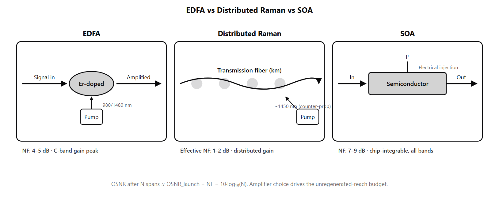
Optical amplifiers are what made DWDM at long-haul reaches practical. Before optical amplification (early 1990s), each span needed full optical-to-electrical-to-optical regeneration; with amplification, dozens of spans can be cascaded before the OSNR budget runs out. The three main amplifier technologies — EDFA, distributed Raman, and SOA — each solve different problems and dominate different deployments. The EDFA (Erbium-Doped Fiber Amplifier) is the workhorse. A short section of erbium-doped fiber is optically pumped with 980 nm or 1480 nm lasers; excited erbium ions amplify signal wavelengths in the 1530–1620 nm range through stimulated emission. The C-band variant (1530–1565 nm) sits at erbium's natural gain peak and has dominated DWDM deployment since the mid-1990s. The L-band variant (1565–1625 nm) uses a longer or differently-doped erbium fiber to extend gain to longer wavelengths. Both have noise figure around 4–5 dB, simultaneous multi-channel gain, and the mechanical simplicity that made deployment-scale optical amplification economic. Distributed Raman amplification (DRA) works by pumping high-power lasers (typically 1450–1480 nm for C-band signal amplification) into the transmission fiber counter-propagating to the signal. The pump light transfers energy to the signal via stimulated Raman scattering in the silica fiber itself, so the signal is amplified continuously along the span rather than at a discrete amplifier at the end. The effective noise figure can be 1–2 dB — or even appear negative relative to a hypothetical lossless-line baseline because the signal is amplified before it has accumulated full-span loss. Raman wins where every dB of OSNR matters: long submarine spans, high-channel-count metro systems, very long unregenerated terrestrial reaches. The Semiconductor Optical Amplifier (SOA) is a compact, chip-integrable amplifier built from a semiconductor gain region similar to a semiconductor laser but without the resonant cavity. SOAs cover wavelength bands EDFA cannot reach (notably the O-band around 1310 nm used in many short-reach datacenter optics, and the S-band), and they integrate naturally with silicon-photonics platforms where compact integration matters. The trade-offs: higher noise figure (7–9 dB) and faster gain dynamics that can cause patterning effects on individual channels and crosstalk between channels. SOAs find roles in transceiver-internal pre-amplifiers, in O-band amplification where EDFA does not apply, and in on-chip integration with silicon-photonics transceivers. The OSNR cascade is the central design equation (see /topics/osnr-ber-q-factor). Each amplifier adds ASE (amplified spontaneous emission) noise proportional to its noise figure; in a cascade of N equal-span equal-gain amplifiers, the ASE adds approximately incoherently and total noise grows as N×ASE_per_amp, while signal power stays at the per-span launch level. The OSNR after N spans follows OSNR_N ≈ OSNR_launch − NF − 10·log10(N). A coherent DP-16QAM channel (see /topics/coherent-modulation-formats) with strong soft-decision FEC needs roughly 16–18 dB OSNR; this cascade-budget calculation is what determines the maximum unregenerated reach. Gain tilt is the daily operational concern. Even a well-designed EDFA has 1–2 dB residual gain tilt across its band; cascaded over 10 amplifiers this becomes 4 dB of inter-channel imbalance. Operators correct tilt with gain-flattening filters inside each EDFA, variable optical attenuators per channel at ROADM degrees, and WSS-based per-channel attenuation in flex-grid systems. Modern DWDM line systems run continuous closed-loop power-equalization across the line, often through SDN-based control.
Why interviewers ask
Optical amplifiers are the single biggest physical-layer determinant of DWDM reach and capacity, so amplifier-architecture questions show up in every optical-transport interview (see /topics/optical-engineer-interview-signals). A candidate who fluently navigates EDFA vs distributed Raman vs SOA trade-offs, the OSNR cascade formula, gain-tilt accumulation, and transient/AGC control is showing the integrated link-budget understanding that long-haul and submarine roles require. The OSNR cascade formula is the deepest interview question. Strong candidates can write out OSNR_N ≈ OSNR_launch − NF − 10·log10(N) from memory, derive it from the assumption of incoherent ASE addition across spans, and connect it to the practical reach limit (typically 20–30 spans for DP-16QAM with strong FEC, less for higher modulations). Weak candidates know that "amplifiers add noise" without quantifying or showing the cascade math. The EDFA vs Raman trade-off is the senior-level deployment question. Strong candidates explain that Raman wins on very long reaches and submarine cables because its low effective noise figure compounds over many spans, but Raman costs more (high-power pumps, safety considerations, operational complexity) so it is reserved for cases where OSNR is binding. Weak candidates either dismiss Raman (have not seen it deployed) or treat it as universally superior (have not faced its cost and operational realities). Gain tilt is probed because it is the daily operational concern. Candidates who name gain-flattening filters and per-channel VOA correction at ROADMs have worked at the line-system level; candidates who treat amplifier gain as a single number across the band have not. The cascaded-tilt accumulation is the math that reveals deployment experience: 0.4 dB residual tilt × 10 spans = 4 dB across-band imbalance. The C+L deployment question ties amplifier choice to channel planning. Strong candidates explain that C-band and L-band need separate EDFA chains (different erbium-fiber designs), and that inter-band Raman crosstalk constraint shapes the per-band power planning. Candidates who treat C+L as "just twice the C-band" miss this engineering depth. See /topics/dwdm-systems-explained for the channel-planning side of this question.
Common mistakes
The most common mistake is treating optical amplification as "free" — as if the amplifier restores both signal power and OSNR. It does not. Amplification restores signal power (with some gain ripple) and adds ASE noise; the OSNR drops by approximately NF + 10·log10(N) across N cascaded amplifiers. Candidates who miss the noise-addition story have not internalized the central long-haul link-budget equation. A second gap is misunderstanding distributed Raman amplification. Some candidates think Raman is just "EDFA in fiber"; it is not — it uses stimulated Raman scattering in the silica fiber itself, with high-power pumps counter-propagating to the signal. The "negative effective noise figure" terminology trips up candidates who do not understand the lossless-line baseline reference. Strong candidates can explain that Raman amplifies the signal continuously along the span so it never accumulates full-span loss before amplification, which beats the post-loss EDFA architecture for noise. A third gap is missing gain tilt. Candidates who describe amplifier gain as a single number across the band have not worked at the line-system level. The 1–2 dB residual tilt per amplifier compounds over 10 spans into 4 dB of across-band imbalance, and operators run continuous power-equalization to manage it. The correction mechanisms — GFF, VOA, WSS per-channel attenuation, launch-side pre-emphasis — are the operational levers candidates should be able to name. A fourth gap is conflating noise figure with insertion loss. NF is the dB ratio between input SNR and output SNR; it measures how much SNR the amplifier consumes. Insertion loss is the dB ratio between input power and output power of a passive component. An EDFA has high gain (no insertion loss in the usual sense) but adds 4–5 dB of noise; an inline VOA has 1 dB insertion loss but adds negligible noise. Candidates who treat these as interchangeable have not yet built the link-budget mental model. A fifth gap is missing transient control. EDFA gain depends on the inversion state, which depends on signal power. When channels are added or dropped, the per-channel gain of survivors swings transiently. Without transient control, the surviving channels can surge in power for milliseconds and trigger downstream errors. Candidates who treat the amplifier as "always-on, always-stable" miss the operational reality that channel changes are routine in deployed networks.
EDFA vs Raman vs SOA — Architecture, Noise, and Best Use
| Property | EDFA | Distributed Raman | SOA |
|---|---|---|---|
| Gain medium | Erbium-doped fiber (discrete) | Transmission fiber (distributed) | Semiconductor gain region |
| Wavelength bands | C-band, L-band (separate designs) | C / L / S (pump-wavelength dependent) | O / S / C / L (broadly tunable) |
| Noise figure (typical) | 4–5 dB | 1–2 dB effective (or sub-zero vs lossless-line baseline) | 7–9 dB |
| Pump laser | 980 nm or 1480 nm, modest power | High power (hundreds of mW) at signal-shifted pump wavelength | Electrical injection, on-chip |
| Integration | Discrete amplifier module | In-line with transmission fiber | On-chip with silicon photonics or InP |
| Best application | Workhorse DWDM amplification (C/L) | Long-haul, submarine, high-channel-count where OSNR is binding | On-chip transceivers; non-EDFA bands |
Sample interview questions
- A long-haul DWDM line system cascades N EDFAs at equal span loss. How does OSNR degrade with N, and what is the practical limit before regeneration is required?
- A. OSNR is constant across the chain — each EDFA exactly restores the original launch OSNR.
- B. Each EDFA adds noise figure NF (typically 4–5 dB for a well-designed C-band EDFA) to the cascade, and OSNR after N spans degrades as OSNR_N ≈ OSNR_launch − NF − 10·log10(N) for equal-loss equal-gain spans. After roughly 20–30 spans the OSNR margin falls below what coherent FEC can correct, and the channel needs regeneration (full optical-to-electrical-to-optical reset). This is why operators tune span lengths to balance per-span loss against EDFA count — shorter spans mean more amplifiers and more accumulated ASE. ✓
- C. Each EDFA improves OSNR because amplification "boosts" the signal.
- D. OSNR degradation is dominated by chromatic dispersion, not amplifier noise.
Option B is correct. The OSNR-cascade formula is one of the foundational link-budget equations in long-haul DWDM design. Each EDFA contributes ASE (amplified spontaneous emission) noise proportional to its noise figure; in a cascade with equal-loss spans where each EDFA restores the launch power, the noise accumulates additively and the OSNR drops by 10·log10(N) plus the noise-figure contribution. Worked example: a C-band EDFA with NF=5 dB and launch OSNR=40 dB/0.1 nm. After 1 span: OSNR ≈ 35 dB. After 10 spans: OSNR ≈ 25 dB. After 30 spans: OSNR ≈ 20 dB. A coherent transceiver running DP-16QAM with strong FEC needs ~16–18 dB OSNR for reliable operation, so the chain runs out of margin in the 20–30 span range. Regeneration restores the signal by converting to electrical, decoding to bits via FEC, and re-encoding to a fresh coherent signal — restoring the OSNR clock. Regenerators are expensive and add latency, so operators design the span plan to maximize the unregenerated reach within OSNR budget. Option A misses that amplification adds noise, not restores OSNR. Option C is wrong — amplification adds noise; it improves received power but degrades OSNR. Option D is wrong; chromatic dispersion is fully compensated in coherent DSP, but OSNR cannot be DSP-recovered once it is gone. Production reality: span lengths of 80–100 km are typical for terrestrial long-haul; submarine systems use shorter spans (40–80 km) with larger arrays of low-noise EDFAs because every dB of OSNR matters over thousands of km.
- When does distributed Raman amplification (DRA) win over an extra EDFA in a long-haul span?
- A. Raman amplification is always worse than EDFA because of higher noise figure.
- B. Distributed Raman pumps backward (counter-propagating) through the fiber span, so the signal is amplified as it travels — the gain builds up along the span instead of being applied at a discrete amplifier at the end. The effective noise figure of a distributed Raman amplifier can be much lower than a discrete EDFA (1–2 dB or even sub-zero relative to a fictional "lossless line"), buying 2–4 dB of OSNR margin. Raman is preferred for very long unregenerated reaches, for high-channel-count systems where OSNR budget is binding, and for submarine systems where any OSNR gain compounds over thousands of km. ✓
- C. Raman amplification only works in the L-band.
- D. Raman amplification requires no pump laser — it is fully passive.
Option B is correct. Distributed Raman amplification uses high-power pump lasers (typically 1450–1480 nm pumps for C-band signal amplification) injected into the fiber counter-propagating to the signal. The pump light transfers energy to the signal through stimulated Raman scattering in the transmission fiber itself, so the signal is amplified continuously along the span rather than at a discrete amplifier site. The effective noise figure of a backward-pumped Raman amplifier can be 1–2 dB, or measured relative to a fictional lossless-line baseline can even appear "negative" — this is because the signal is amplified before it has accumulated full-span loss. When Raman wins: - Very long spans (above 100 km) where the EDFA-only OSNR cascade is tight - High-channel-count systems where every dB of OSNR margin keeps more channels alive - Submarine systems where the OSNR clock matters over thousands of km - C+L systems where Raman can also help equalize gain tilt across the band When EDFA-only is better: - Shorter spans (under 80 km) where EDFA noise figure is already low enough - Cost-sensitive deployments (Raman pumps add real cost and operational complexity) - Spans where high-power Raman pumps would cause nonlinear penalties or safety concerns Option A inverts the noise-figure relationship. Option C is wrong — Raman gain in silica fiber works across the optical range, with appropriate pump wavelength shifts for different signal bands. Option D is wrong; Raman requires a high-power pump laser, very much an active component. Production reality: hybrid EDFA+Raman amplification is common — the Raman provides low-noise distributed gain along the span, the EDFA provides additional booster gain at the end. The combination optimizes OSNR per dollar.
- A cascade of 10 EDFAs in a DWDM line shows progressively worsening per-channel power balance — the short-wavelength channels arrive 4 dB stronger than the long-wavelength channels by the end. What is the dominant mechanism, and how is it corrected?
- A. Random per-channel power drift; nothing systematic can be done.
- B. Gain tilt across the EDFA band: erbium gain is not perfectly flat across 1530–1565 nm, and small per-amplifier tilt accumulates over cascaded amplifiers, producing dB-level inter-channel imbalance after 5–10 spans. Operators correct this with (a) gain-flattening filters (GFF) integrated into each EDFA to pre-tilt and counteract the natural tilt, (b) variable optical attenuators per channel at ROADM degrees to equalize at the end of each section, and (c) WSS-based per-channel attenuation at each ROADM node. Without these corrections, the strong channels run into nonlinear penalties and the weak channels run out of OSNR margin. ✓
- C. Stimulated Raman scattering, which always shifts energy from short wavelengths to long wavelengths.
- D. L-band leakage from a misconfigured filter.
Option B is correct. EDFA gain across the C-band has a natural shape that is not perfectly flat — the gain peaks around 1530–1535 nm and falls off toward both edges. Even a well-designed EDFA has 1–2 dB of residual tilt across the band after the manufacturer's gain-flattening filter. This per-amplifier tilt accumulates across N cascaded amplifiers, producing dB-level inter-channel power imbalance: after 10 amplifiers a 0.4 dB per-stage tilt becomes 4 dB total tilt across the band. Operators correct gain tilt through several mechanisms: - Gain-flattening filters (GFF) inside each EDFA — passive optical filters that pre-tilt the gain to cancel the natural EDFA shape - Variable optical attenuators (VOA) per channel inside ROADM degrees — actively attenuate the strong channels to equalize the band - Wavelength-selective switch (WSS) per-channel attenuation — modern flex-grid ROADMs use WSS that can apply per-channel attenuation with finer granularity - Pre-emphasis at the transmitter — operators can launch the weaker channels with slightly higher power to compensate the predictable end-to-end tilt Why it matters: if gain tilt is not corrected, the strong channels run into nonlinear-penalty territory (Kerr effects worsen at high power, generating crosstalk to other channels) while the weak channels lose OSNR margin and may fail FEC. Option A misses the systematic mechanism. Option C confuses gain tilt with SRS — SRS does transfer energy from short to long wavelengths, but it is a separate effect that becomes significant only at very high channel powers; gain tilt is the dominant cause of moderate accumulated imbalance. Option D is a possible cause of band-edge anomalies but not a systematic tilt across the band. Production reality: channel-power equalization is one of the daily operational tasks for any high-utilization DWDM line system, often automated through the SDN control plane with per-channel power monitoring at every ROADM.
Frequently asked questions
- What is an EDFA?
- An EDFA (Erbium-Doped Fiber Amplifier) is the most widely deployed optical amplifier in DWDM systems. A short section of erbium-doped fiber is pumped optically (typically with 980 nm or 1480 nm pump lasers); the excited erbium ions amplify signal wavelengths in the 1530–1620 nm range through stimulated emission. EDFAs are popular because they are wavelength-band-matched (their natural gain peak falls in the C-band where most DWDM operates), they amplify many channels simultaneously with one gain stage, they have low noise figure (4–5 dB typical), and they are mechanically and electrically simple. C-band EDFAs cover roughly 1530–1565 nm; L-band EDFAs use longer or differently-doped erbium fiber to cover 1565–1625 nm.
- What is distributed Raman amplification?
- Distributed Raman amplification (DRA) uses high-power pump lasers (typically 1450–1480 nm for C-band signal amplification) injected counter-propagating into the transmission fiber itself. The pump light transfers energy to the signal via stimulated Raman scattering in the silica fiber, so the signal is amplified continuously as it travels along the span rather than at a discrete amplifier at the end. The effective noise figure of distributed Raman can be 1–2 dB (or even appear negative relative to a fictional lossless-line baseline), which is significantly better than the 4–5 dB of a discrete EDFA. Raman is the technology of choice for very long unregenerated reaches, high-channel-count systems, and submarine cables where every dB of OSNR margin matters.
- What is an SOA (Semiconductor Optical Amplifier)?
- An SOA is an optical amplifier built from a semiconductor gain medium, similar in physics to a semiconductor laser but without the resonant cavity. SOAs are compact, integrable on chip (especially in silicon-photonics platforms where co-integration with other photonic functions is possible), and can amplify across wavelengths that EDFAs do not reach (notably the O-band around 1310 nm and the S-band). The down sides: SOAs have higher noise figure (typically 7–9 dB), and they exhibit faster gain dynamics that can cause patterning effects and crosstalk between channels. SOAs are used in wavelength bands where EDFAs do not work, in chip-integrated transceivers where compact integration matters, and in pre-amplifier roles within transceivers.
- What is optical amplifier noise figure?
- Noise figure (NF) is the dB ratio between the SNR at the amplifier input and the SNR at its output — it measures how much SNR the amplifier consumes. A low-noise amplifier has low NF (more SNR preserved). For optical amplifiers, the noise figure is closely related to the spontaneous-emission factor: NF ≈ 2·n_sp where n_sp is the population-inversion factor (n_sp = 1 for a perfectly inverted gain medium gives NF = 3 dB, the quantum limit). A well-designed C-band EDFA achieves NF around 4–5 dB. Distributed Raman amplification achieves effective NF in the 1–2 dB range. SOA NF is typically 7–9 dB. The noise figure is the dominant amplifier-design specification because it bounds the OSNR cascade across long links.
- How does amplified spontaneous emission (ASE) accumulate across a cascade?
- Each EDFA contributes ASE noise proportional to its noise figure and gain. In a cascade of N equal-gain equal-span amplifiers, the ASE adds approximately incoherently (since each amplifier's ASE is independent), so the total noise power scales as N×ASE_per_amp. The OSNR after the cascade therefore drops as OSNR_N ≈ OSNR_launch − NF − 10·log10(N) for equal-loss spans (the formula assumes each amplifier restores the per-span loss). This is the fundamental OSNR-cascade formula and the reason long-haul links face a hard reach limit before regeneration becomes necessary — typical 20–30 spans for coherent DP-16QAM with strong FEC, less for higher-order modulations that need more OSNR margin.
- What is gain tilt and how is it corrected?
- Gain tilt is the variation of an amplifier's gain across the wavelength band. Erbium's natural gain shape peaks around 1530–1535 nm and falls off toward longer wavelengths; even a manufactured EDFA with a gain-flattening filter retains 1–2 dB of residual tilt. Across N cascaded amplifiers this accumulates: 10 cascaded EDFAs with 0.4 dB residual tilt each produce 4 dB of inter-channel imbalance across the band. Operators correct this with (1) gain-flattening filters (GFF) inside each EDFA, (2) variable optical attenuators (VOA) per channel at ROADM degrees, (3) per-channel attenuation in WSS at flex-grid ROADMs, and (4) launch-side pre-emphasis. Without correction, the band's strong channels suffer nonlinear penalties and the weak channels lose OSNR margin.
- What is EDFA transient control?
- EDFA gain is dynamic: when channels are added or dropped, the per-channel gain of the surviving channels swings transiently as the erbium population redistributes. Without transient control, dropping half the channels in a fully-loaded system can cause the remaining channels to surge in power for milliseconds — potentially driving downstream amplifiers into saturation and causing bit errors. EDFA transient control uses fast pump-power feedback to hold the total gain (or total output power) constant on the millisecond timescale, suppressing per-channel transients. Operators activate transient control during planned channel adds and drops and during fault-recovery scenarios where many channels may swap state simultaneously.
- How does EDFA AGC (automatic gain control) work?
- AGC stabilizes the EDFA's per-channel gain (or per-channel output power) against varying input conditions. The control loop monitors the input or output total power and adjusts the pump power to maintain the target gain. AGC is essential because the EDFA's gain depends on the population-inversion state, which is affected by signal power and pump power — a fixed pump current would yield very different per-channel gains depending on how many channels are present and how strong they are. Modern EDFAs offer multiple AGC modes: total-output-power control (maintains total amp output regardless of channel count), per-channel-gain control (maintains the gain each channel sees), and gain-spectrum control (manages tilt across the band). The choice depends on whether the operator wants stable per-channel output power or stable per-channel gain in changing channel-count conditions.
Related topics
Siblings
- DWDM Systems Explained: C-Band, L-Band, and the 400G/800G Era
- OSNR, BER, Q-factor: How Optical Engineers Measure Link Quality
- Optical Fiber Impairments Explained: CD, PMD, Nonlinearity
- ROADM & Wavelength Switching Explained: WSS, Degrees, CDC
- Coherent Optical Detection: How DSPs Replaced Direct Detection
- Optical Engineer Interview Signals: What Interviewers Probe
- Optical Fiber Standards: G.652 vs G.654 vs G.657 vs Hollow-Core
Essential AI-Native Skills for EDFA vs Raman vs SOA: Optical Amplifier Comparison
Modern engineering work increasingly uses AI tools for design and code review, debugging, documentation, test and testbench generation, and workflow automation. The goal is not to let AI replace engineering judgment — it is to move faster while keeping verification discipline.
- Use AI to explain unfamiliar code, logs, waveforms, datasheets, or test failures.
- Break large problems into small, reviewable steps you can verify independently.
- Ask AI for hypotheses, then validate them against tests, measurements, simulations, or lab data.
- Version-control your analysis scripts, testbenches, and configs — keep changes small and reviewable.
- Document your assumptions, design tradeoffs, and debugging decisions.
- Verify AI output before trusting it: run the checks that fit the domain — unit tests, linters, simulations, or bench/lab measurements.
- Review AI output for correctness, edge cases, and real-world consequences.
EDFA vs Raman vs SOA: Optical Amplifier Comparison — coming to the question bank
The adaptive practice engine is already live for core wireless, RF, and ML systems. EDFA vs Raman vs SOA: Optical Amplifier Comparison isn't covered in the question bank yet — get notified when it's added.