DSP Fundamentals Interview Prep
DSP fundamentals interview prep — sampling theorem, z-transform, FIR vs IIR filters, fixed-point arithmetic, and windowing.
Quick answer
Digital Signal Processing (DSP) is the mathematics and engineering of representing real-world continuous signals as sequences of numerical samples and operating on those sequences - filtering, transforming, decimating, modulating, demodulating - using arithmetic on a programmable processor or fixed-function hardware.
DSP fundamentals are the gating examination at every signal-processing, ML, wireless, and embedded-DSP role.
Editorial review
Written by
CompoundLearn editorial team
Wireless / RF / hardware engineering
Reviewed by
CompoundLearn editorial team
Wireless / RF / hardware engineering
Last reviewed
Built from curated topic maps, editorial validation, and subject-matter review so the page stays aligned with the interview intent and the current content pipeline.
Key points
- DSP interviews test fluency across continuous-time, sampled discrete-time, and finite-word-length implementations — the sampling theorem, z-transform/DFT, FIR vs IIR choice, multirate structures, and fixed-point effects.
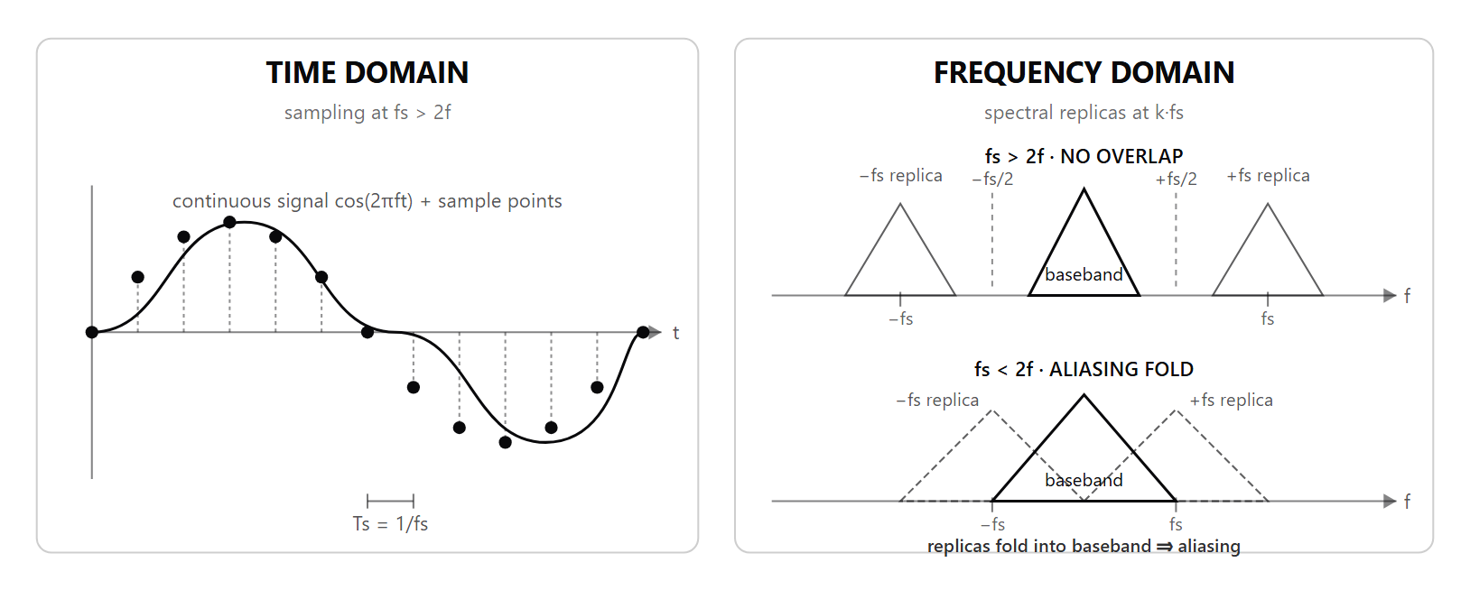
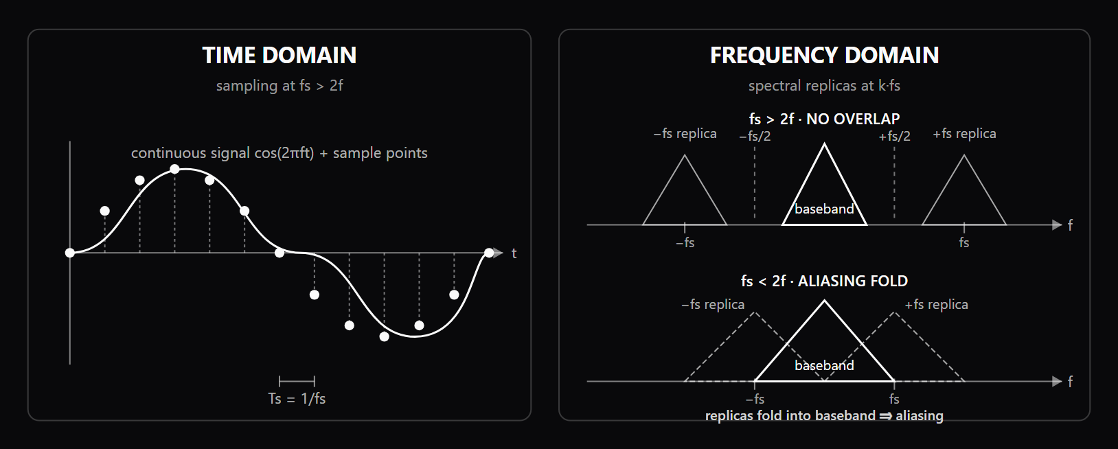
- State the sampling theorem strictly: a signal band-limited below B Hz reconstructs from samples taken at a rate strictly greater than 2B; sampling exactly at 2B fails when energy sits at the band edge.
- FIR vs IIR is a phase-versus-cost trade: a symmetric FIR gives exact linear phase (constant group delay) but needs more taps; a low-order IIR hits a sharp magnitude response cheaply but adds nonlinear phase and fixed-point limit-cycle risk.
- Pole-zero placement governs behavior: a causal filter is BIBO-stable when all poles sit inside the unit circle, and minimum-phase when all zeros sit inside it too.
- The FFT computes the same DFT in O(N log N) instead of O(N²) — it is an exact algorithm, not a different or approximate transform.
- Windowing trades main-lobe width against sidelobe leakage; a rectangular record is still a window, and oversampling plus decimation lowers in-band quantization noise by about 3 dB per octave.
What it is
Digital Signal Processing (DSP) is the mathematics and engineering of representing real-world continuous signals as sequences of numerical samples and operating on those sequences - filtering, transforming, decimating, modulating, demodulating - using arithmetic on a programmable processor or fixed-function hardware. DSP underpins every modern communication standard (see /topics/communication-systems), audio codec, image-processing pipeline, radar, sonar, and instrumentation system; the same algorithm may run on DSP cores, ARM NEON, x86 SIMD, FPGA fabric, or a dedicated ASIC. The technology stack starts with the Nyquist sampling theorem as the physical floor, uses the z-transform, DTFT, and DFT as analytical tools, and builds practical systems from FIR/IIR filters, multirate structures, fixed-point scaling, and the FFT as the workhorse algorithm. The Shannon sampling theorem is the entry point: a band-limited signal can be reconstructed from samples taken above twice its highest frequency, but practical systems oversample to relax anti-alias filters, create guard band, and gain processing SNR through decimation. Filter design splits into FIR (unconditionally stable, linear-phase capable when symmetric, computationally heavier) and IIR (low-order sharp responses, nonlinear phase, pole-placement and limit-cycle concerns). The DFT and its FFT algorithms power spectral estimation, fast convolution, image filters, audio analyzers, and filter banks; understanding bin spacing, spectral leakage, coherent gain, and equivalent noise bandwidth is non-negotiable. Multirate processing - decimation, interpolation, polyphase decomposition, and CIC filters - underpins high-throughput receivers and software-defined radio. Quantization, dithering, and fixed-point arithmetic determine whether the algorithm survives implementation on the target hardware.
Why interviewers ask
DSP fundamentals are the gating examination at every signal-processing, ML, wireless, and embedded-DSP role. The questions probe whether a candidate can move fluently across continuous-time signals (see /topics/signals-and-systems), sampled discrete-time signals, and finite-word-length implementations. Interviewers use DSP basics as a depth check: candidates who memorize "FIR is stable, IIR is faster" without explaining linear phase, pole-zero placement, or limit-cycle behavior fall out fast. A good DSP interview also probes intuition: what is the impulse response of an ideal low-pass filter and why is it not realizable, how do you choose between Hann and Hamming windows for a tone-detection application, what does an FFT bin actually represent in continuous-frequency terms, why does decimation alias high-frequency components if you do not pre-filter. ML candidates increasingly hit DSP questions because spectrograms, mel filterbanks, and other front-end feature extractors are DSP at heart. Wireless candidates need DSP to reason about matched filtering, sample-rate conversion, IQ imbalance compensation, and channel estimation. Hardware candidates need DSP to bind multipliers to DSP slices, decide between FIR taps and IIR biquads, and pick fixed-point Q-formats. The breadth of relevance makes DSP fundamentals an unusually high-leverage prep target.
Common mistakes
Several patterns recur. First, sloppy statements of the sampling theorem: the strict inequality (sample rate strictly greater than 2B) matters in formal arguments, even if practical systems sample well above. Saying "sample at twice the bandwidth" without acknowledging the theorem requires you to strictly exceed twice the bandwidth (or that sampling exactly at 2B fails when energy is non-zero at the band edge) is an instant red flag. Second, conflating linear phase with no phase distortion: a linear-phase filter introduces a constant group delay, which is "no distortion" only in the sense that all frequencies experience the same delay. Third, careless FIR-versus-IIR rules of thumb: candidates say "FIR for stability, IIR for sharpness" without acknowledging that fixed-point IIR implementations often suffer limit cycles or instability under quantization, even when the floating-point design is provably stable. Fourth, FFT confusion: candidates assume FFT bin index k corresponds to a single discrete frequency, missing that the rectangular implicit window leaks energy into adjacent bins, and that bin width depends on N and sample rate. Fifth, ignoring fixed-point growth: a multiply of two Q1.15 numbers produces Q2.30, which must be re-scaled and rounded before storage; getting that wrong burns dynamic range or saturates. Sixth, treating windowing as cosmetic — choosing rectangular for everything — when the right window is what determines whether you can resolve two close tones at all.
Sample interview questions
- Why sample a 9 kHz ADC input at 24 kHz instead of exactly 18 kHz under the Nyquist sampling theorem?
- A. Sampling at 24 kHz changes the input bandwidth from 9 kHz to 12 kHz, so the ADC no longer needs an anti-alias filter.
- B. Real anti-alias filters need transition band above 9 kHz; 24 kHz leaves guard band, and later decimation can reduce out-of-band quantization noise. ✓
- C. Nyquist requires the sample rate to equal exactly twice the highest input tone, so 18 kHz is mathematically safer than 24 kHz.
- D. Oversampling removes aperture jitter and thermal noise from the ADC front end before any digital filter runs.
Option B is correct because Nyquist says a strictly band-limited signal with maximum frequency B can be reconstructed when fs > 2B. A real analog input is not brick-wall limited, and a real anti-alias filter has a finite transition band, so sampling exactly at 18 kHz for a 9 kHz signal leaves no room for filter roll-off. Sampling at 24 kHz leaves a guard band from 9 kHz to 12 kHz, lets the analog filter be physically realizable, and allows a digital decimator to remove out-of-band quantization noise after conversion. Option A is incorrect because sampling faster does not change the input signal bandwidth. It changes where aliases would land and how much guard band the anti-alias filter has. Option C is incorrect because the theorem uses a strict greater-than relationship for ideal reconstruction. Exact 2B sampling is a limiting case that fails when nonzero energy sits at the band edge. Option D is incorrect because oversampling does not remove jitter or thermal noise. It can spread quantization noise over a wider Nyquist band so filtering and decimation lower in-band noise, but analog front-end noise sources still exist.
- When should a DSP engineer choose a symmetric FIR over a low-order IIR for an audio equalizer when the added latency is tolerable?
- A. When the design needs feedback poles near the unit circle, because symmetric FIR filters rely on pole placement to sharpen the transition band.
- B. When coefficient memory must be minimized, because a linear-phase FIR generally needs fewer taps than an equivalent IIR section.
- C. When constant group delay matters and the FIR latency is acceptable: symmetric FIR coefficients give exact linear phase, while an IIR usually reaches the same magnitude shape with fewer multiplies and lower latency but nonlinear phase. ✓
- D. When phase response is irrelevant, because FIR symmetry mainly improves arithmetic speed rather than waveform shape.
Option C is correct because a real-coefficient FIR with symmetric taps has exact linear phase, so all passband frequency components experience the same group delay. That preserves transient shape in audio, measurement, and control paths where phase distortion matters. A low-order IIR can achieve a sharp magnitude response with far fewer multiplies, but its poles introduce nonlinear phase and frequency-dependent group delay. The FIR advantage is conditional: its linear phase costs latency (roughly half the tap count) and can introduce symmetric pre-ringing, so for a low-latency audio EQ a minimum-phase IIR is sometimes preferred despite the nonlinear phase. Option A is incorrect because FIR filters have no feedback poles except the delay-line structure at the origin in the transfer-function representation. Pole placement near the unit circle is the IIR design mechanism. Option B is incorrect because the usual trade is the reverse. FIR filters often require many more taps to match the magnitude selectivity of a low-order IIR. Option D is incorrect because the main engineering reason to pick a symmetric FIR is phase behavior, not raw arithmetic speed. The FIR may be highly parallel and stable, but it usually costs more operations for the same transition width.
- In a causal digital filter, what do pole-zero locations in the z-plane say about stability and minimum phase?
- A. BIBO stability requires all zeros inside the unit circle; pole locations mainly set passband ripple and can sit outside if the impulse response is finite.
- B. Minimum phase means the poles and zeros mirror each other across the unit circle, producing a flat group delay across the passband.
- C. A causal IIR is stable whenever its pole-zero plot has more zeros than poles, because the extra zeros cancel feedback growth.
- D. BIBO stability requires all poles inside the unit circle; minimum phase further requires zeros inside the unit circle, with any all-pass factor (unity magnitude response) carrying phase but not magnitude. ✓
Option D is correct because a causal LTI digital filter is BIBO stable when its region of convergence includes the unit circle, which for a causal rational transfer function means every pole is strictly inside |z| = 1. Minimum phase adds the condition that every zero is also inside the unit circle; zeros outside can be reflected inside by factoring out an all-pass term that preserves magnitude but changes phase and group delay. Option A is incorrect because poles, not zeros, determine stability for a causal IIR. A zero outside the unit circle makes the system non-minimum-phase, but it does not by itself make the filter unstable. Option B is incorrect because mirrored pole-zero pairs are the signature of all-pass factors, not the definition of minimum phase. All-pass factors can create substantial phase and group-delay variation while leaving magnitude unchanged. Option C is incorrect because counting poles and zeros is not a stability test. A single uncanceled pole outside the unit circle causes an exponentially growing impulse response regardless of how many zeros appear elsewhere.
- At N = 4096 samples, what distinguishes the DFT from a radix-2 FFT, and why does it matter for implementation cost?
- A. FFT is a different mathematical transform from the DFT, so it produces a different spectrum for the same samples.
- B. The DFT is the mathematical transform from N samples to N frequency bins; a radix-2 FFT is an algorithm that computes that same DFT using twiddle-factor symmetries in O(N log N). ✓
- C. FFT is limited to power-of-2 signal lengths, so non-radix-2 records require direct DFT evaluation.
- D. FFT is an approximation of the DFT that sacrifices accuracy for speed.
Option B is correct because the DFT is the definition: X[k] = sum_n x[n] exp(-j 2 pi kn/N). A radix-2 FFT is a family of algorithms that evaluates the same sum by recursively decomposing even and odd samples and reusing twiddle factors. Direct DFT evaluation costs O(N^2) multiply-adds; the FFT costs O(N log N), which is why large spectral analyzers, convolution engines, and filter banks are practical. Option A is incorrect because "FFT is a different mathematical transform from the DFT" is the misconception. The FFT computes the same DFT samples; it changes the algorithm, not the transform definition. Option C is incorrect because radix-2 is limited to N = 2^k, but FFT algorithms are not limited to power-of-2 lengths. Mixed-radix, split-radix, and Bluestein forms handle other sizes. Option D is incorrect because "FFT is an approximation of the DFT" is the misconception. The FFT is exact up to normal finite-precision arithmetic; it exploits twiddle-factor symmetry rather than sacrificing accuracy.
- In spectral windowing, why would an analyzer choose a Blackman or Kaiser window instead of a rectangular window?
- A. Not applying a window means no windowing effect, so a rectangular record is neutral and avoids sidelobe artifacts.
- B. There is one best window function for all applications, and Blackman or Kaiser should be used by default.
- C. To lower sidelobe leakage from strong tones; the trade is a wider main lobe plus corrections for coherent gain and equivalent noise bandwidth. ✓
- D. Windowing helps reduce aliasing artifacts, so it can replace the anti-alias filter before sampling.
Option C is correct because the finite record is multiplied by a time-domain window before the DFT. A rectangular window has the narrowest main lobe but high sidelobes, so a strong tone leaks into distant bins. Blackman and high-beta Kaiser windows taper the record more aggressively, pushing sidelobes down at the cost of a wider main lobe. Measurement code must also correct for coherent gain when estimating tone amplitude and for equivalent noise bandwidth when estimating noise power. Option A is incorrect because "not applying a window means no windowing effect" is the misconception. Truncating a record to N samples is rectangular windowing, and that rectangular window has high sidelobes. Option B is incorrect because "there is one best window function for all applications" is the misconception. Every window trades main-lobe width against sidelobe level, so the right choice depends on whether resolution or dynamic range matters more. Option D is incorrect because "windowing helps reduce aliasing artifacts" is the misconception. Windowing addresses spectral leakage from finite observation length; aliasing is a sample-rate and anti-alias-filter problem.
- In multirate DSP receiver design, why do decimators and interpolators place filters around the sample-rate change?
- A. Decimation filters run after downsampling to undo aliases, while interpolation filters run before upsampling to create images that the DAC can smooth.
- B. The filters are optional bookkeeping steps; the sample-rate change itself preserves spectra if the original signal was represented with floating-point samples.
- C. CIC filters are used because they have exact flat passbands, so compensation filters are unnecessary in software-defined radio chains.
- D. Decimation filters remove energy that would alias before downsampling; interpolation filters remove zero-stuffing images after upsampling, with polyphase and CIC forms reducing arithmetic. ✓
Option D is correct because downsampling by M compresses the spectrum by M and folds any content above the new Nyquist frequency into baseband. The anti-alias low-pass must therefore run before the sample drop. Upsampling by L inserts zeros, which creates repeated spectral images around multiples of the original lower-rate spectrum; an anti-imaging low-pass removes those images after insertion. Polyphase implementations avoid computing discarded samples, and CIC filters provide multiplier-free coarse rate changes that are attractive in ADC and SDR front ends. Option A is incorrect because aliases created by downsampling cannot be separated afterward; once high-frequency content folds into baseband it is indistinguishable from desired signal content. Interpolation imaging also appears after zero insertion, so the image-reject filter belongs after the upsampler. Option B is incorrect because sample representation does not protect against spectral folding. Floating-point precision reduces arithmetic quantization but does not change sampling theory. Option C is incorrect because CIC filters have passband droop. They are efficient integrator-comb structures, but practical receivers often add a compensation FIR after the CIC stage.
- For an ideal N-bit ADC quantization-noise model, what does SNR = 6.02N + 1.76 dB assume, and how can oversampling and dither help?
- A. It assumes a full-scale sine and uncorrelated uniform quantization error; oversampling spreads noise over more bandwidth for decimation, while dither decorrelates distortion. ✓
- B. It assumes every input waveform has the same crest factor, so oversampling adds 6.02 dB per octave and dither increases effective number of bits directly.
- C. It assumes quantization noise is below thermal noise for any ADC, so digital filtering after conversion cannot change in-band SNR.
- D. It assumes the ADC transfer function is nonlinear; dither removes missing codes and oversampling repairs integral nonlinearity.
Option A is correct because the textbook 6.02N + 1.76 dB result comes from quantizing a full-scale sine wave with an ideal uniform quantizer whose error is modeled as white, uniformly distributed, and uncorrelated with the input. Oversampling spreads the same total quantization-noise power across a wider Nyquist band; a decimation low-pass keeps the signal band and rejects out-of-band noise, improving in-band SNR by about 3 dB per doubling of oversampling ratio without noise shaping. Dither adds a small random signal so deterministic quantization distortion becomes noise-like and easier to average or filter. Option B is incorrect because crest factor matters: a signal below full scale or with a high peak-to-average ratio will not achieve the textbook sine-wave SNR. Plain oversampling without noise shaping improves in-band SNR by about 3 dB per octave, equivalent to about half a bit, not 6.02 dB per octave. Option C is incorrect because quantization noise can dominate or sit below thermal noise depending on converter design and signal level. Digital decimation absolutely can reduce in-band quantization noise after oversampling. Option D is incorrect because the ideal formula assumes a linear quantizer with uniform steps. Dither can mask small nonlinear artifacts and missing-code patterns in some converters, but it does not repair integral nonlinearity.
Frequently asked questions
- What does the Shannon sampling theorem actually say?
- A continuous-time signal that is strictly band-limited to frequencies below B Hz can be perfectly reconstructed from samples taken at any rate strictly greater than 2B (the minimum required sample rate, often called the critical sampling rate). The reconstruction is by sinc interpolation. The theorem assumes a perfectly band-limited input — in practice no signal is — so anti-alias filtering before the ADC and reconstruction filtering after the DAC are both required in practice (barring an already-band-limited or sufficiently oversampled input). A common confusion: the theorem says >2B, not >=2B; sampling exactly at 2B works only when the signal energy at exactly B Hz is zero. Modern systems often oversample (to relax anti-alias filter slope, push noise out of band, and gain processing SNR through decimation).
- What is the difference between FIR and IIR filters?
- A Finite Impulse Response filter computes its output as a weighted sum of a finite window of past inputs; the impulse response is finite length. FIRs are unconditionally stable (no feedback), can be designed for exact linear phase, and parallelize cleanly on DSPs and FPGAs. The cost is order: a steep transition typically needs many more taps than an equivalent IIR. An Infinite Impulse Response filter feeds back past output samples; the impulse response decays but is technically infinite. IIRs achieve sharp magnitude responses with low order (Butterworth, Chebyshev, elliptic prototypes) but introduce non-linear phase, can become unstable under fixed-point quantization, and require care in coefficient scaling and limit-cycle behavior. Pick FIR when phase linearity matters; pick IIR when computation budget is tight and phase distortion is tolerable.
- How is the z-transform related to the Fourier transform?
- The z-transform of a discrete-time sequence x[n] is X(z) = sum_n x[n] z^-n, where z is a complex variable (see /topics/complex-analysis). The discrete-time Fourier transform (DTFT) is the z-transform evaluated on the unit circle, z = e^(j*omega). The unit circle plays the role the imaginary axis does for continuous-time Laplace-versus-Fourier. The location of poles relative to the unit circle determines stability (poles inside = stable causal system); zeros control the nulls of the magnitude response. Designing a digital filter is essentially placing poles and zeros, then mapping that pole-zero diagram to a Direct-Form structure (Direct Form I, II, transposed, biquad cascade) trading numerical sensitivity against compute cost.
- What is fixed-point arithmetic and where does it bite?
- Fixed-point arithmetic represents fractional numbers as integers with an implicit binary scale (Q-format: Q1.15, Q2.14, etc.). It is fast and resource-efficient — perfect for FPGAs, DSP cores, and microcontrollers without an FPU. The traps are dynamic range (the integer cannot grow indefinitely without saturating or overflowing) and quantization noise (each bit truncation adds a noise floor). Multiplications grow the operand width and require careful right-shifting and rounding before the result is stored. IIR filters with poles near the unit circle are particularly susceptible to fixed-point limit cycles — small-amplitude oscillations driven by quantization that float forever. The standard mitigations are scale analysis up-front, saturation arithmetic at intermediate stages, and convert-then-decide rounding rather than truncation.
- What is windowing and why does it matter for spectrum estimation?
- Spectrum estimation via the DFT implicitly views a finite captured segment as one period of a periodic signal. If the segment's endpoints do not match, the implied periodic extension has a discontinuity, which spreads spectral energy across many bins (spectral leakage). A window function (Hann, Hamming, Blackman, Kaiser, flat-top) tapers the segment so the endpoints are near zero, reducing leakage at the cost of widening the main lobe. Different windows trade main-lobe width against side-lobe height: rectangular (no window) has narrow main lobe but high sidelobes; Blackman has very low sidelobes but a wide main lobe; Kaiser parameterizes the tradeoff with a single shape parameter. Choosing a window is a deliberate choice driven by what you need to resolve.
- What is the difference between linear convolution and circular convolution?
- Linear convolution is the physical convolution of two finite sequences without wrap-around: an input of length N convolved with an impulse response of length M produces N + M - 1 output samples. Circular convolution wraps indices modulo a chosen length L, so tail energy that would extend past the end of the block folds back to the beginning. The DFT naturally diagonalizes circular convolution, which is why FFT-based fast convolution must zero-pad the input and filter to at least N + M - 1 before transforming. Without that padding, the FFT result contains time-domain aliasing: the wrapped tail is added to the first samples of the block. Overlap-add and overlap-save are the production block-processing methods that use this fact safely.
- Why are FIR filters always stable?
- An FIR filter has no feedback path: its output is a finite weighted sum of present and past input samples. If the input is bounded and the tap coefficients are finite, then the output is bounded by the input bound times the sum of absolute tap magnitudes. That bounded-input bounded-output argument holds regardless of coefficient values, so an FIR cannot create the runaway exponential response associated with an IIR pole outside the unit circle. In z-transform terms, an FIR transfer function has a finite polynomial numerator and only delay-line poles at the origin. The practical caveat is implementation arithmetic: fixed-point overflow can still corrupt an FIR output, but that is arithmetic saturation, not filter-theory instability.
- What does group delay tell you about a filter?
- Group delay is the negative derivative of phase with respect to angular frequency: -d phi / d omega. It tells you how much a narrowband component centered at each frequency is delayed by the filter. A flat group-delay curve across the passband means all frequencies arrive with the same delay, so pulses and transients keep their shape aside from amplitude shaping. A curved group-delay response means different spectral components arrive at different times, which smears waveforms even if the magnitude response looks acceptable. This is the key reason sample question fO7qY1Im chooses a symmetric FIR for phase-sensitive audio or instrumentation paths; its linear phase gives constant group delay, while a low-order IIR typically buys magnitude selectivity by accepting group-delay distortion.
Related topics
Pillar
Siblings
- Wireless Foundations
- OFDM Explained: Subcarriers, Cyclic Prefix, PAPR, and OFDMA
- MIMO Explained: Spatial Multiplexing, Rank, Massive MIMO
- Beamforming Interview Guide: Analog vs Digital vs Hybrid
- Antenna Design
- FPGA Design
- Signals and Systems
- Kalman Filter Interview Questions: EKF, UKF & Q/R Tuning
- Communication Systems
Practice
Essential AI-Native Skills for DSP Fundamentals
Modern engineering work increasingly uses AI tools for design and code review, debugging, documentation, test and testbench generation, and workflow automation. The goal is not to let AI replace engineering judgment — it is to move faster while keeping verification discipline.
- Use AI to explain unfamiliar code, logs, waveforms, datasheets, or test failures.
- Break large problems into small, reviewable steps you can verify independently.
- Ask AI for hypotheses, then validate them against tests, measurements, simulations, or lab data.
- Version-control your analysis scripts, testbenches, and configs — keep changes small and reviewable.
- Document your assumptions, design tradeoffs, and debugging decisions.
- Verify AI output before trusting it: run the checks that fit the domain — unit tests, linters, simulations, or bench/lab measurements.
- Review AI output for correctness, edge cases, and real-world consequences.